Routing the cables
■ Guidelines for routing the cables
• Route the motor cable away from other cables.
• Avoid long parallel runs of power cables with other cables. See the allowed minimum
distances below. You can install motor cables of several drives in parallel.
• Install the motor cable, input power cable and control cables on separate trays.
• Make sure that the cable trays have good electrical bonding to each other and to the
grounding electrodes. You can use aluminum tray systems to improve local equalizing
of potential.
• Where control cables must cross power cables, make sure they are arranged at an
angle as near to 90 degrees as possible.
• Do not run extra cables through the drive.
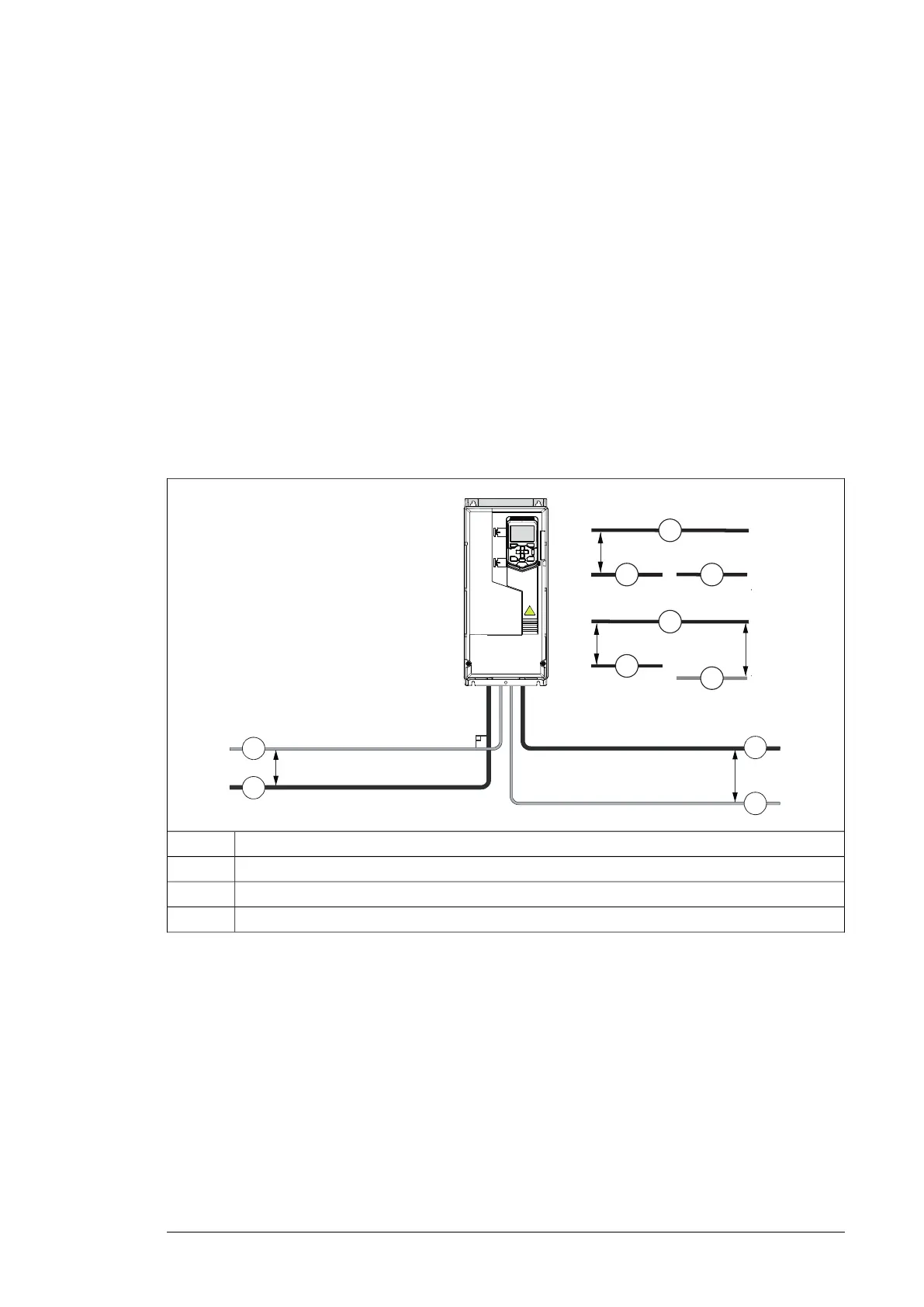
This figure illustrates the cable routing guidelines with an example drive.
min. 200 mm (8 in)
90°
*min. 500 mm (20 in)
1
2
3
3
2
1
4
min. 300 mm (12 in)
2
4
3
min. 300 mm (12 in)
*
Motor cable1
Input power cable2
Control cable3
Brake resistor or chopper cable (if any)4
Electrical planning guidelines 29

 Loading...


