30 AO2000-LS25 LASER ANALYZERS | OI/AO2000-LS25-EN REV. D
… 4 Design and function
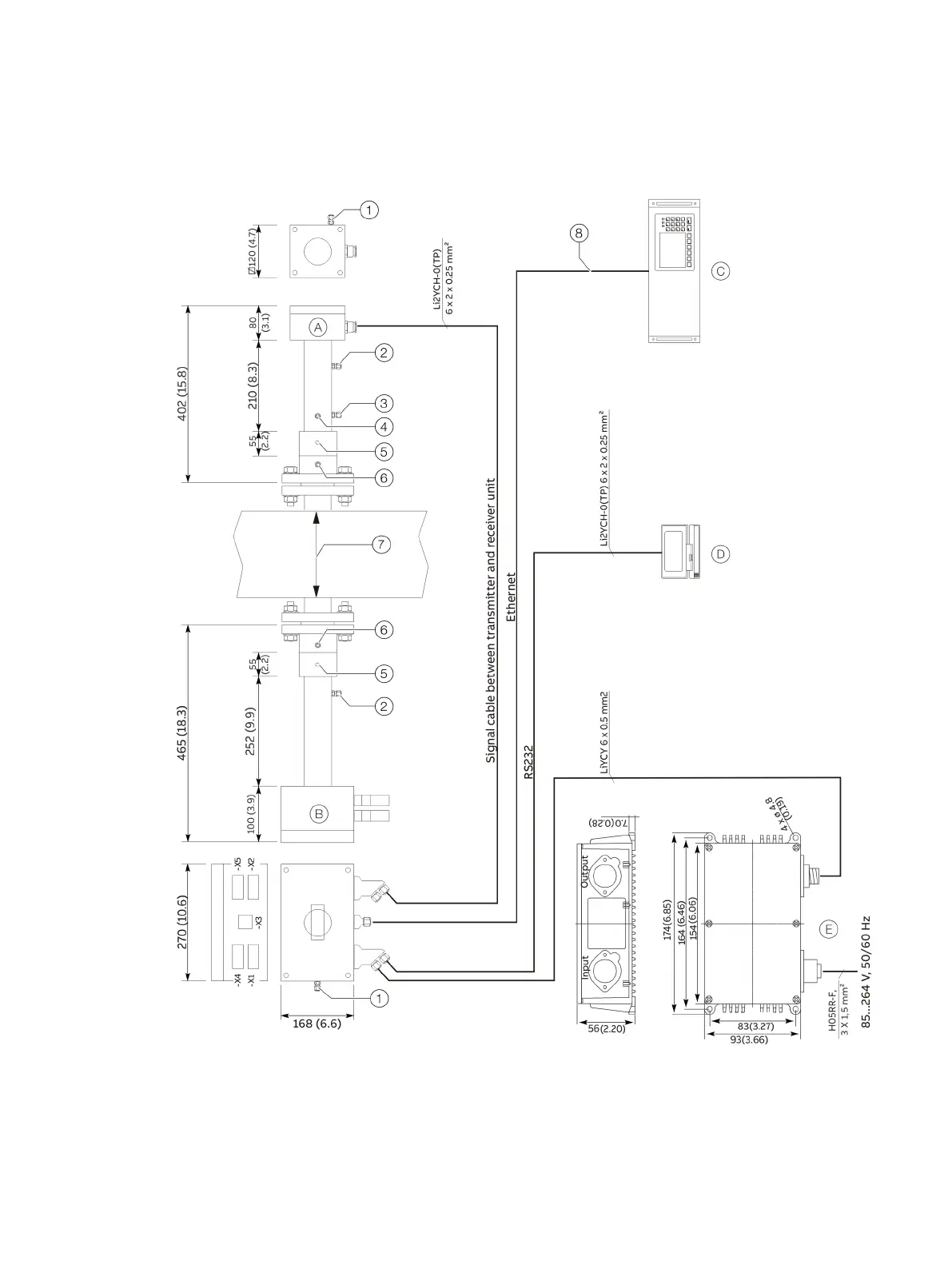
Dimensions, position of the purging connections and installation of cables
(Deviations in explosion-proof designs and compact variants are possible)
Receiver unit
Transmitter unit
AO2000 central unit
Service PC
Power supply unit
Purge gas outlet (housing purging), ∅ 6 mm
Purge gas inlet (housing purging), ∅ 6 mm
Calibration gas outlet, ∅ 6 mm
Calibration gas outlet, ∅ 6 mm
Tap hole M8
Purge gas inlet (flange purging), ∅ 10 mm
Optical distance 0.5 to 15 m (1.6 to 49.2 ft)
CAT5 cable, for outdoor use or for direct
earthing, with double PVC sheath
Figure 12: Block diagram of AO2000-LS25