48 AO2000-LS25 LASER ANALYZERS | OI/AO2000-LS25-EN REV. D
… 9 Commissioning
… Align analyzer with laser alignment
device
Pre-aligning the purging flanges
Pre-alignment is carried out in three steps:
1. Mount the laser pointer on the transmitter unit purging
flange and the focusing screen on the receiver unit
purging flange. Perform pre-alignment as described
below.
2. Mount the laser pointer on the receiver unit purging
flange and the focusing screen on the transmitter unit
purging flange. Perform pre-alignment as described
below.
3. Re-mount the laser pointer on the transmitter unit
purging flange and the focusing screen on the receiver
unit purging flange. Perform pre-alignment as described
below.
• After completion of the pre-alignment, refit the
transmitter and receiver units and perform fine-tuning
according to Setting the maximum transmission on
page 48.
Performing pre-alignment
1. Unscrew the 6 stud screws (item
6 in Figure 32) until the
ends of the screws no longer stick out of the holes.
2. Switch on the laser pointer.
3. Align the purging flanges by adjusting the 4 screws (item
5
in Figure 32) until the laser beam hits the center of the
focusing screen.
4. Screw in the 4 stud screws until they stop so that the setting
is fixed.
5. Switch off the laser pointer.
6. Remove the laser pointer and focusing screen.
Setting the maximum transmission
Fine-tuning of the transmitter and receiver units is performed by
measuring the adjustment voltage at the connectors of the
signal cable to ensure that a maximum signal (transmission) is
achieved.
The adjustment voltage varies from 0 V at 0 % transmission to
−3V (typically) at 100 % transmission.
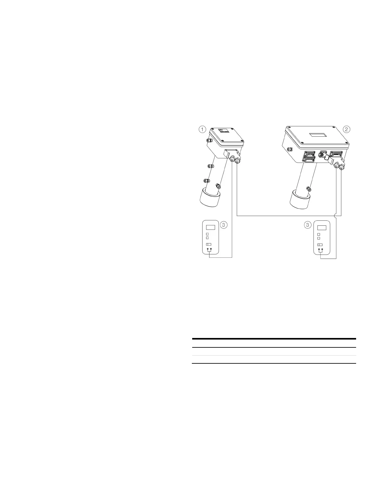
Receiver unit
Transmitter unit
Voltmeter
Figure 33: Measurement of adjustment voltage
As shown in Figure 33, by connecting a voltmeter to the
adjustment connector, the adjustment voltage
(Lineup+/Lineup−) is measured in the connector housing of the
signal cable of the transmitter and receiver units.
Lineup+
Table 29: Pin assignment adjustment voltage
* Design with integrated validation cell