AO2000-LS25 LASER ANALYZERS | OI/AO2000-LS25-EN REV. D 45
Connecting analog inputs (option)
Active (with separate power supply) or passive (power supply
from the LS25) sensors can be connected.
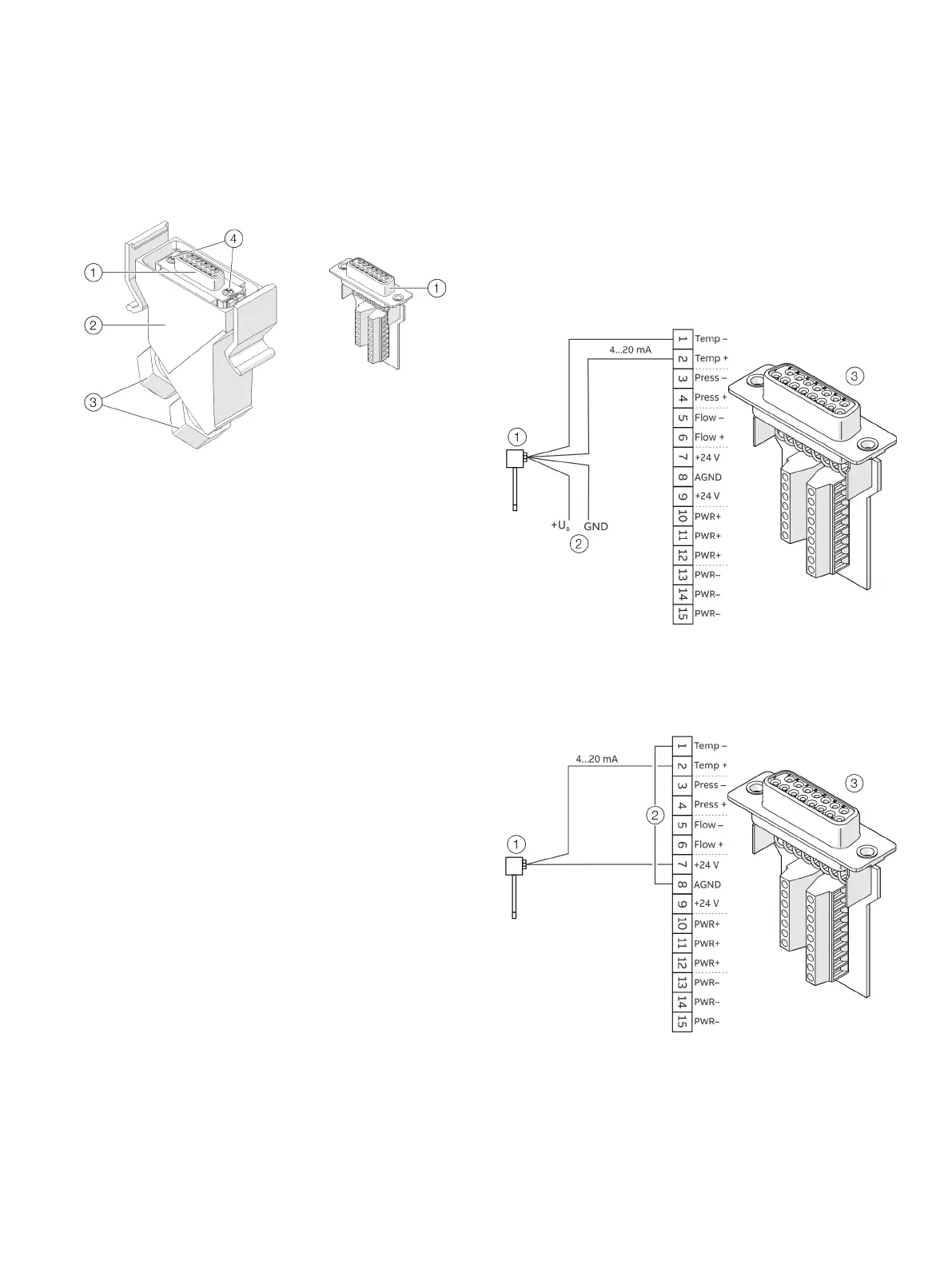
Plug insert
Connector housing
Cable glands
Fixing screws plug insert
Figure 28: Power supply / analog inputs connector
1. Switch off the power supply.
2. Disconnect the power supply / analog inputs connector from
the transmitter unit.
3. Loosen the cable glands and the plug insert and pull it out of
the plug housing.
4. Feed the wire for the external sensors into the plug housing
through the free cable gland.
5. Connect the cables to the screw terminals of the plug insert
according to Figure 29 “Active sensor” or Figure 30 “Passive
sensor”.
• Connection assignment, see Transmitter unit – power
supply / analog inputs on page 20.
• To connect the sensors, use cables with a cross-section
of 0.14 to 0.5 mm
2
(AWG 26 to 20) (ABB recommends
0.25 mm
2
).
• The outer cable diameter (1× per cable gland) must be in
the 3 to 9 mm range.
• The internal burden of the analog input is 100 Ω.
• For passive sensors, a 24 V power supply with a maximum
current load capacity of 80 mA is available (terminals
+24 V/AGND).
6. Reinstall the plug insert in the plug housing and tighten it.
Tighten the cable glands.
7. Attach the power supply / analog inputs connector to the
transmitter unit.
Note
• The connection examples show the connection of a
temperature sensor. Pressure and flow sensors are
connected to the corresponding inputs (Press / Flow).
• The connection examples show the connection with plug,
devices with terminal blocks are connected according to the
corresponding connection assignments.
Sensor (Active)
External power supply sensor
Power supply and analog inputs plug insert
Figure 29: Connection example for analog input, active (example, temperature sensor)
Sensor (Active)
Bridge
Power supply and analog inputs plug insert
Figure 30: Connection example for analog input, passive (example, temperature sensor)