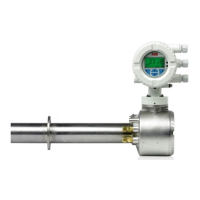
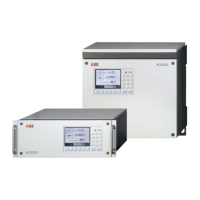
Water Hardness Analyzer
AW101 Testomat 10 AW101 Testomat® Block Diagram
IM/AW101 Rev. C 19
10.1 Terminal Block Identification
No. Te rmin a l Type Function Note
– PE IN Mains – Protective earth (5x) Earth/Ground
1 2 L N IN
Mains, L = Live
Mains, N = Neutral
Mains input
115 V, 230 V or 24 V AC
3 to 5
6 to 8
n l OUT
Neutral, switched (8x)
Live, switched (8x)
Mains voltage,
max. 4 A
9
10
11
LV1 OUT
Limit value output 1 – Normally closed
Limit value output 1 – Common
Limit value output 1 – Normally open
Volt-free relay output,
max. load 240 V AC, 4 A
12
13
14
LV2 OUT
Limit value output 2 – Normally closed
Limit value output 2 – Common
Limit value output 2 – Normally open
Volt-free relay output,
max. load 240 V AC, 4 A
15
16
17
Alarm OUT
Fault message – Normally closed
Fault message – Common
Fault message – Normally open
Volt-free relay output,
max. load 240 V AC, 4 A
18
19
Stop 2 IN External analysis stop Common earth for inputs
Only for volt-free normally
open/normally closed contact
20 21 IN 2 IN Water meter input Common earth for inputs
Only for volt-free normally
open/normally closed contact
Note technical data of turbine
22 23 OUT + OUT – OUT 0 or 4 to 20mA
Current output 22 + (0/4 to 20 mA)
23 –
24 + OUT +12 V for Hall-Sensor (turbine)
Note technical data of turbine. Max.
power input of sensor must not
exceed 20 mA
Fig. 10.2 Terminal Block Labels
 Loading...


