Water Hardness Analyzer
AW101 Testomat 4 Description of Displays and Operating Features
6 IM/AW101 Rev. C
4 Description of Displays and
Operating Features
a Status of Limit Value Displays
Displays the status of the limit values LV1 and LV2.
b Text Display
Displays the current analysis, all important status results
and programming data in a 2-line LCD.
c Alarm
Displays a function fault.
d Power Switch
The On/Off switch is located on the right-hand side panel.
e Unit Fuse (inside the unit)
Protects outputs against overload and short circuit.
f Analysis Message
Displays current analysis.
g Programming Keys (Cursor block with ENTER)
These keys are used to enter all values and programming
data.
h 'Manual' – manual start of an analysis.
i 'STANDBY' – manual analysis stop/standby.
j 'Alarm' – cancels alarm message.
k I-Key
Access all unit information.
l M-key
Access the programming menu.
4.1 Display Functions
Status of limit values 1 and 2
1: The red display lamp is lit if limit value 1 i(LV1) s
reached or exceeded. It turns green if the measured value
falls below the set limit value.
2: The red display lamp is lit if limit value 2 (LV2) is
reached or exceeded. It turns green if the measured value
falls below the set limit value.
Status and measured value display:
In continuous operation the current measured value is
shown in the upper line.
When the measured value falls below the measuring range
’<’ is displayed: for example, <0.05 °dH
When the measured value exceeds the measuring range
’>’ is displayed: for example, >10.0 °dH
When the analysis interval is stopped while in operation
(Analysis Stop), STANDBY and measured value are
displayed alternately.
The icon appears if the low-level reagent alarm is
active.
4.2 Limit Value Displays
The adjustable limit values are shown in the bottom display line.
4.3 Alarm Message
A fault condition is signalled by a red light.
Error messages are displayed alternately with the normal display
text and can only be deleted by cancellation and correction of
the fault.
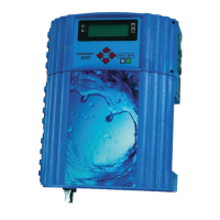
Fig. 4.1 Display Functions
 Loading...


