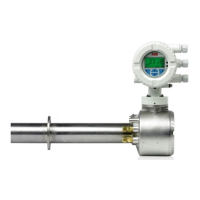
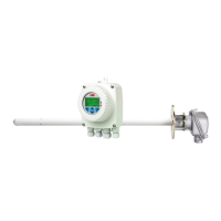
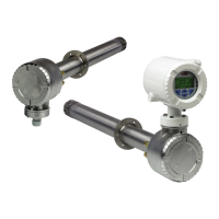
Endura AZ20 series probe
Combustion oxygen monitor 3 Mechanical Installation
IM/AZ20P–EN Rev. G 11
3.6 Overall Dimensions
3.6.1 Remote Endura AZ20 Probe
3.6.2 Integral Endura AZ20 Probe
Dimensions in mm (in)
Fig. 3.12 Overall Dimensions – Remote Endura AZ20 Probe
384 (15.2)
(8 .0 )
Ø 135 (5.3)
Ø 62 (2.4)
55
(2.2)
203
Dimensions from Flange to Probe Cell in m (ft)
0.5, 1.0, 1.5, 2.0, 2.5, 3.0, 3.5 or 4.0
(1.7, 3.3, 5.0, 6.6, 8.2, 9.9, 11.5, 13.1)
For flange dimensions refer to Section 3.7, page 12
For probe weights refer to page 16
Dimensions in mm (in)
Fig. 3.13 Overall Dimensions – Integral Endura AZ20 Probe
390 (15.3)
40 7 (1 6. 0)
Ø 135 (5.3)
341
(13.4)
Ø 62 (2.4)
168 (6.6)
55
(2.2)
For flange dimensions refer to Section 3.7, page 12
For probe weights refer to page 16
Dimensions from Flange to Probe Cell in m (ft)
0.5, 1.0, 1.5, 2.0, 2.5, 3.0, 3.5 or 4.0
(1.7, 3.3, 5.0, 6.6, 8.2, 9.9, 11.5, 13.1)
 Loading...
