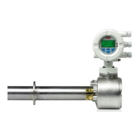
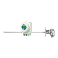
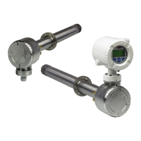
Endura AZ20 series probe
Combustion oxygen monitor 5 Start-up and Operation
IM/AZ20P–EN Rev. G 27
5.2.2 AutoCal System without Restrictors
To set up an AutoCal system without restrictors:
1. Make test gas and reference air connections as detailed in
Section 3.5.2, page 9 (remote or integral transmitter).
2. Turn on Test Gas 1 and set the pressure to a nominal
1bar (15 psi).
3. At the transmitter, check the Calibrate / AutoCal Hardware
/ Hardware Type parameter is Internal.
4. At the transmitter, open the
'Test Gas 1' valve by selecting:
Calibrate / AutoCal Hardware / Valve Manual Control /
Test Gas 1 and pressing to open the valve.
A small icon is displayed to indicate the valve is in the
Open position:
5. Fine tune Test Gas 1 pressure to 1 bar (15 psi) and set the
flow on the flowmeter to 2.2 l / min (4.662 scfh).
6. Turn gas off at the transmitter by pressing , then turn
Test Gas 1 off at the supply.
7. Repeat steps 2 to 6 for Test Gas 2 (if present).
8. Refer to IM/AZ20E-EN to perform a calibration when
required.
5.2.3 Non-AutoCal System with Restrictors
To set up an Non-AutoCal system with restrictors:
1. Make test gas and reference air connections as detailed in
Section 3.5.3, page 10 (remote or integral transmitter).
2. Turn on Test Gas 1 and adjust the pressure to
1 bar (15 psi).
3. Turn Test Gas 1 off at the supply.
4. Repeat steps 2 to 4 for Test Gas 2 (if present), connect the
Test Gas 2 line to the probe’s external TG1 connection.
5. Refer to IM/AZ20E-EN to perform a calibration when
required.
5.2.4 Non-AutoCal System without Restrictors
To set up an Non-AutoCal system without restrictors:
1. Make test gas and reference air connections as detailed in
Section 3.5.3, page 10 (remote or integral transmitter).
2. Turn on Test Gas 1, adjust the pressure to 1 bar (15 psi)
and the flow on the flowmeter to 2.2 l / min (4.662 scfh).
3. Turn Test Gas 1 off at the supply.
4. Repeat steps 2 to 4 for Test Gas 2 (if present), connecting
the Test Gas 2 line to the probe’s external TG1
connection.
5. Refer to IM/AZ20E-EN to perform a calibration when
required.
Valve icon
'Open' position
Valve icon
'Closed' position
Note. Test Gas 1 and 2 connections are made to the
probe’s external Test Gas 1 (TG1) connection and
must be switched manually – see section 3.5.3, page
10.
Note. Test Gas 1 and 2 connections are made to the
probe’s external Test Gas 1 (TG1) connection and
must be switched manually – see section 3.5.3, page
10.
 Loading...
