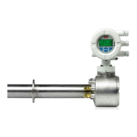
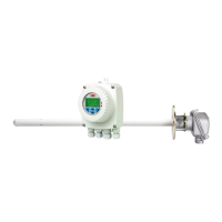
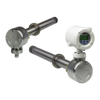
Endura AZ20 series probe
Combustion oxygen monitor Appendix B – Endura AZ20/ZFG2 Replacement Probe
IM/AZ20P–EN Rev. G 33
B.2 ZDT-FG Analyzer Connections
B.2.1 Disconnecting the Existing ZFG2 Probe
Referring to Fig. B.4:
1. Unlock and remove the lower panel
A from the ZDT-FG
analyzer, remove the 2 shroud retaining screws
B and
remove shroud C.
2. Disconnect wires from heater terminal D, cell terminal
E, thermocouple terminal F and loosen conduit entry
gland G.
3. For analyzers using the conduit’s Reference Air line,
disconnect existing reference air supply H, remove the
conduit and proceed to step 5.
4. For analyzers using an external Reference Air connection,
leave the existing reference air supply pipe
I in place.
B.2.2 Connecting the Endura AZ20/ZFG2 Replacement
Probe
Referring to Fig. B.4:
1. Pass the new conduit through entry gland
G and tighten
the gland.
2. Make connections to heater terminal D, cell terminal E,
thermocouple terminal
F as shown in Table B.2.
3. For probes using the conduit’s Reference Air supply,
connect conduit reference air line H.
4. Refit shroud C and secure it with the 2 shroud retaining
screws B.
5. Refit the lower panel A.
Warning. Before disconnecting existing ZFG2 conduit, or
connecting the new Endura AZ20/ZFG2 replacement probe
conduit, ensure the power supply, any powered control
circuits and high common-mode voltages are switched off.
Note. For analyzers without internal pumps, the Reference
Air connection is made directly to the probe’s external 'Ref.
Air' connection – see Fig. B.1, page 30.
ZDT-FG
Ter m i n al
Connection Wire
HHeaterBrown
HHeaterBlue
E Heater Earth
Green /
Yellow
Cell + Oxygen Input (+ve) Red
Cell – Oxygen Input (–ve) Blue
Cell SCN Oxygen Input Screen Braid
TC+ Thermocouple (+ve) White
TC– Thermocouple (–ve) Blue
Table B.2 Conduit Connections at ZDT-FG Analyzer
Fig. B.4 Endura AZ20/ZFG2 Replacement Probe
Conduit Connections at ZDT-FG Analyzer
*External air line to internal pump (used if conduit air line is not
connected). For analyzers with no internal pump, the Reference
air line connects directly to the probe’s external 'Ref. Air'
connection – see Fig. B.1, page 30.
I
n
t
e
r
n
a
l
External*
 Loading...
