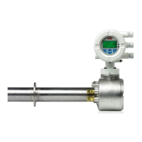
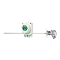
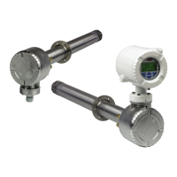
Endura AZ20 series probe
Combustion oxygen monitor 4 Connections
20 IM/AZ20P–EN Rev. G
4.3 Electrical Connections
4.3.1 Endura AZ20 Probe Transmitter Connections
Referring to Fig. 4.3:
1. Unscrew and remove the probe end cap
A.
2. Pass probe cable B through probe entry gland C
taking care not to disturb the existing wiring D.
3. Remove terminal plug E from probe terminal block F.
4. Make terminal plug connections as shown in Table 4.1:
5. Carefully connect terminal plug
E into probe terminal
block F taking care not to disturb the existing wiring D.
6. For probes fitted with AutoCal, proceed to Section 4.3.2,
page 21.
7. For probes without AutoCal, tighten cable gland C.
8. Refit the probe end cap
A and tighten hand-tight.
9. Refer to IM/AZ20E-EN for transmitter connections.
Notes.
Non-AutoCal probes are not fitted with the 6-way
AutoCal terminal block or pressure switch / solenoid
valve block.
For probes fitted with AutoCal, make standard
connections (steps 1 to 5), then AutoCal connections
as detailed in Section 4.3.2, page 21.
For non-AutoCal probes, retain the unused AutoCal
wires to allow for a future upgrade – see Table 4.2 for
AutoCal wire colors.
Terminal /
Cable Color
Tag I D Tx Connection
Violet ACJC
Pt1000 Cold
Junction Compensation
Grey ACJC
Pt1000 Cold
Junction Compensation
Red Cell + Oxygen Input (+ve)
Black Cell – Oxygen Input (–ve)
Green TC+ Thermocouple (+ve)
White TC – Thermocouple (–ve)
Light Yellow
(Sleeved Screens)
SCN
Screens 1 and 2
(Screens 1 and 2 must be
connected for correct
operation)
Brown H Oven
Blue H Oven
Table 4.1 Probe Transmitter Cable Connections
Fig. 4.3 Endura AZ20 Probe Transmitter Cable Connections
Transmitter Terminal
Plug Connected
Cable
Color Label
 Loading...
