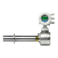
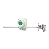
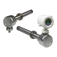
Endura AZ20 series probe
Combustion oxygen monitor Appendix B – Endura AZ20/ZFG2 Replacement Probe
IM/AZ20P–EN Rev. G 31
B.1 Endura AZ20/ZFG2 Replacement Probe Conduit Electrical Connections
B.1.1 Electrical Connections
Referring to Fig. B.2:
1. Unscrew and remove probe end cap
A.
2. Pass conduit B through probe entry gland C taking
care not to disturb the probe’s internal wiring D.
3. Tighten cable gland C.
4. Make connections
E to colored terminal plug
connections as shown in Table B.1:
5. Make reference air connections as detailed in Appendix
B.1.2, page 32.
Important.
For removal of the existing ZFG2 probe (complete with
its conduit assembly) and installation of the Endura
AZ20/ZFG2 replacement probe, refer to the ZFG2
probe manual (this manual can be downloaded from
the ABB web site at (www.abb.com) or by clicking the
following link: IM/ZFG2).
The Endura AZ20/ZFG2 replacement probe must be
installed using the new conduit supplied with the
probe.
Terminal / Cable
Color
Tag ID Connection
Violet
Not Used
Grey
Red Cell + Oxygen Input (+ve)
Blue Cell – Oxygen Input (–ve)
White TC+ Thermocouple (+ve)
Blue TC – Thermocouple (–ve)
Braid Cell SCN Screen
Brown H Heater
Blue H Heater
Table B.1 Probe Transmitter Cable Connections
Fig. B.2 Endura AZ20/ZFG2 Replacement Probe –
Conduit Electrical Connections
Colored Terminal
Plug connections
 Loading...
