54
Installation and commissioning guide
2750 515-1 EN, REV. 14, 2020-06-26
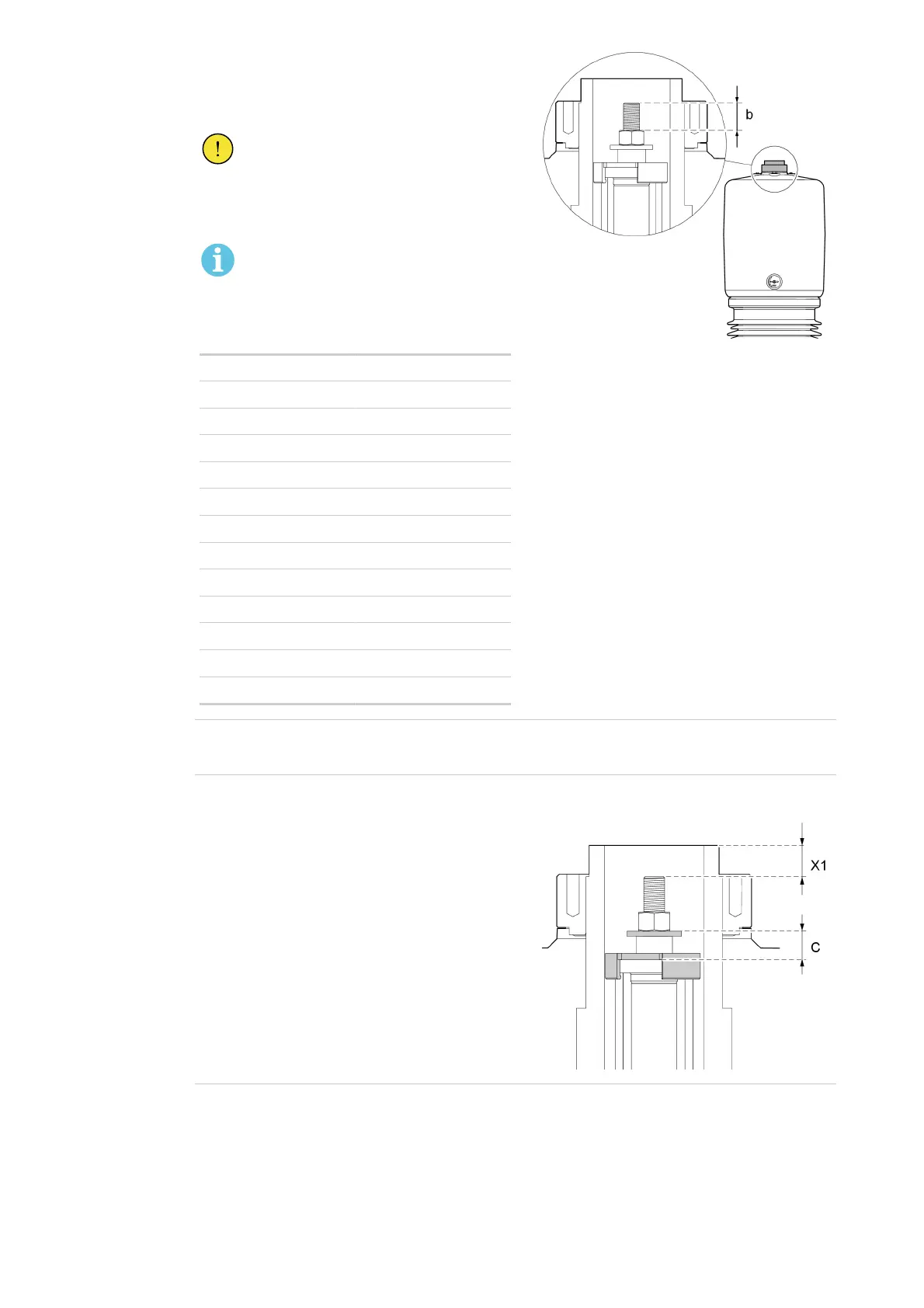
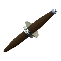
3. Turn the nut clockwise until you get the correct
extension (b).
Distance (b) = (a) + extension, refer to the table.
CAUTION!
Make sure that you do not overtighten
the nut. Use a torque wrench set to
140 Nm.
NOTE!
One turn of the nut corresponds to a
2 mm extension of the draw rod.
Type Extension
GOE 250 - 210 3.5 mm ±1.0
GOE 380 - 300 3.5 mm ±1.0
GOE 650 - 500 5.0 mm ±1.0
GOE 950 - 650 7.0 mm ±2.0
GOE 1050 - 750 9.0 mm ±2.0
GOE 1175 - 850 9.5 mm ±2.0
GOE 1300 - 1050 12.0 mm ±2.0
GOE 1425 - 1150 12.0 mm ±2.0
GOE 1550 - 1175 15.0 mm ±2.0
GOE 1675 - 1300 15.0 mm ±2.0
GOE 1800 - 1360 15.0 mm ±2.0
GOE 2550 - 1600 18.0 mm ±2.0
GOE 2550 - 1675 18.0 mm ±2.0
G005050
4.
Make sure with a torque wrench that the nut is tightened with a torque of more than 70 Nm and less
than 140 Nm.
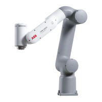
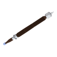
5.
When installing the bushing at site:
1. Measure the values (X1) and (c).
2. Record the values in Measurement record,
page 87, for future reference.
Keep the document with the substation
documentation.
G006758
End of instruction