Operation Manual / TPR56-F + TPR61-F
8 Disassembly and assembly / 8.6 Dismantling and installing the tur-
bine diffuser and nozzle ring
© Copyright 2018 . All rights reserved. HZTL2490_EN Revision D May 2018
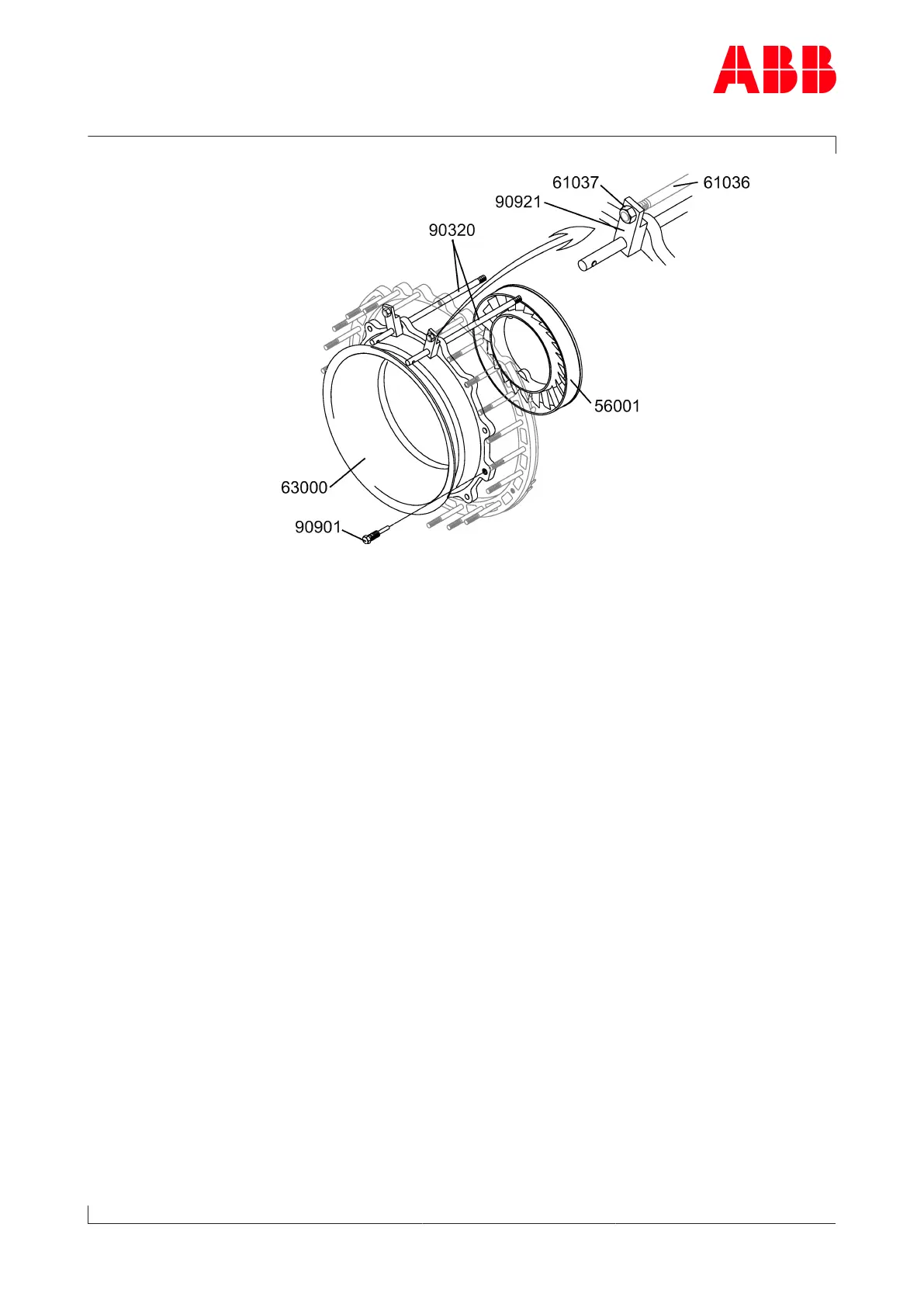
u Replace two screws (61056) in the gas outlet casing with two guide
studs (90320) in the upper section of the turbine diffuser (63000).
u Fit clamps (90921) over the guide studs (90320) and the studs
(61036).
u To secure the work, screw nuts (61037) onto the start of the stud
threads (61036).
u Remove the remaining screws (61056) and Verbus Ripp® washers
(61057).
u Press the turbine diffuser (63000) free using the press-off screws
(90901) and pull it out it until the clamp (90921) is up against the nut
(61037).
u Remove the nut (61037) and clamps (90921) from the stud.
u Fully withdraw the turbine diffuser and remove it.
u Remove the guide studs (90320).
u Pull nozzle ring (56001) forward and remove.
Installing the turbine diffuser and nozzle ring
u Install the nozzle ring and turbine diffuser in the reverse order of re-
moval.
u Coat the screw threads with high-temperature grease.
u Align nozzle ring with holes or cams in gas inlet casing.
Page 66 / 79