OI-LLT100-EN Rev. D | User Guide 29
10 Configuring process alarms
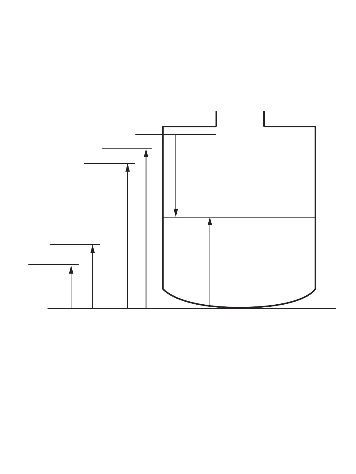
Figure 20 Limits variables diagram
By design, when a monitored process is within defined limits,
the LLT100 analog signal output is between 4mA and 20mA.
If the instrument detects a failure, the analog signal is driven
higher or lower.
The Process Alarm menu allows you to configure saturation
and failure alarms when the process variable (PV) goes outside
these limits.
10.1 Setting failure mode
The LLT100 allows you to set which alarm value will trigger the
failure mode (see “Setting measurement value high and low
limits” on page 19). Generally, the High value will trigger
this mode.
To set which alarm will trigger the failure mode:
1. From the Process Alarm menu, select Failure Mode.
2. From the Failure Mode screen, select High or Low to
determine which alarm will trigger the failure mode.
3. Press OK.
10.2 Defining alarm delays
A delay was implemented to prevent raising alarms too quickly
after the threshold has been reached.
To set an alarm delay:
1. From the Process Alarm menu, select Alarm Delay.
2. From the Alarm Delay screen, edit the length of time during
which an alarm can persist before the alarm is actually
raised.
3. Press OK.
Vessel height
Ullage
Level
High High Alarm
High Alarm
Low Low Alarm
Low Alarm