Configuring communications 69
—
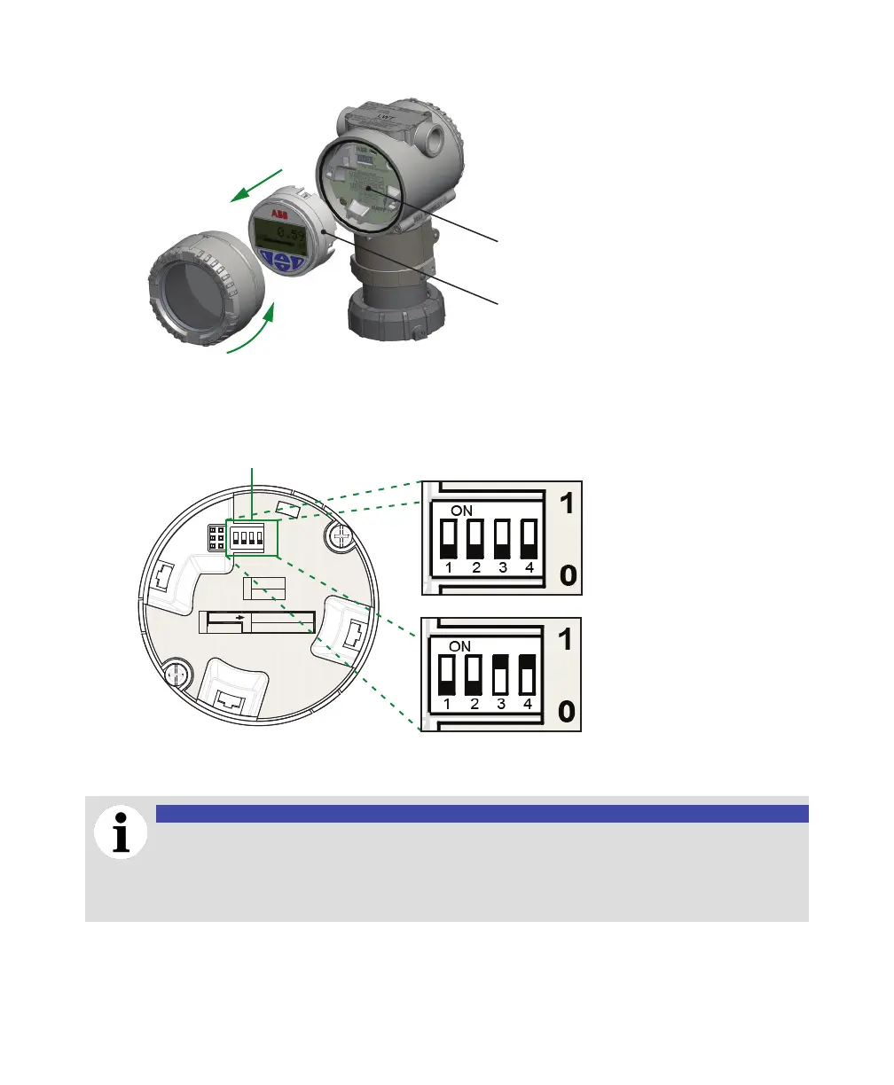
Figure 49 Pulling out the HMI board
HMI board
Communication board
4 On the communication board, set dip switches 3 and 4 to position 1 (see Figure 50). Your LWT
instrument is now ready to be configured via your preferred software tool.
—
Figure 50 Modbus communication board
ENABLE
1
NV FORMAT
0
PROTOCOL MODE
1
0
SW 3
1
SW 1
0
DISABLE
MODBUS
TM
P/N : 3KXL001060U0400
ENABLE
DISABLE
SW 4
CONFIG / HART-RS485
OPERATE / MODBUS
1 2 3 4
ON
Dip switches
Configuration
HART/RS485
Operation
Modbus
For more information on the configuration setup that you need to start communicating with your
instrument, see “Configuring the LWT300 with a computer” on page 60.
NOTICE
When you are done configuring the instrument remotely via HART, you must toggle the
communication mode back to Operation (switches 3 and 4 to position 0); otherwise the
instrument will not be able to resume sending data when reconnected to the Modbus
network.

 Loading...


