MegaFlex 1000 to 1600 UPS User Manual / REV-A
2. Close the “Q1 – External UPS Output Circuit Breaker” (Pos. I).
• LED ALARM and Acoustical Alarm are activated.
3. Confirm the closure of the “Q1 – External UPS Output Circuit Breaker” (Pos. I).
Perform the “Q1 Status CONFIRM” command from the screen:
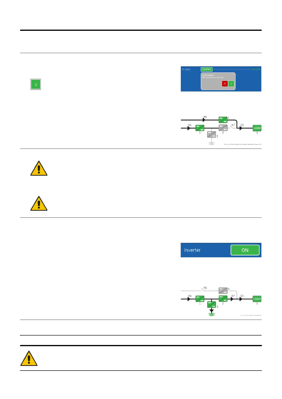
Commands 3 / Q1 status / CONFIRM.
• LED ALARM and Acoustical Alarm turn OFF.
• Rectifier starts automatically. LED 1 (Rectifier) blinking, indicates Soft-start.
• At the end of Rectifier Soft-start the LED 1 (Rectifier) remains lit.
The Synoptic Diagram must display the status
“Load supplied by Automatic Bypass”.
Ensure the LED 1 (Rectifier) is lit before carrying out this procedure (4).
It indicates that the DC-link 1 and DC-
link 2 has reached 400Vdc (see screen MEASURES /
Rectifier)!
Verify the right DC polarities on both side of the switch/fuse holder!
4. Connect the Battery to the UPS by closing the “External Battery Breaker” (Pos. I).
Note!
Before performing the next procedure (5) make sure that the LED 1 (Rectifier) and
(Booster/Battery charger) is lit.
5. Insert the Inverter performing the command "Inverter ON".
Before performing this procedure (5) make sure that the LED 1 (Rectifier) and LED 3 (Booster/Battery
Perform the “Inverter ON” command from the screen:
Commands 1 / Inverter / ON.
• Soft-start of the Inverter indicated with blinking LED 2 (Inverter).
• At the end of Inverter Soft-start the LED 2 (Inverter) remains lit.
• Load is now supplied from Inverter.
• LED ALARM turns OFF and the LED LOAD PROTECTED must be lit.
The Synoptic Diagram must display the status
“Load supplied by Inverter”.
Note!
The Battery
must be charged for at least 10 hours, in order to ensure the full backup runtime in case
of a Utility Failure.
 Loading...