


P
Pamela RoblesSep 10, 2025
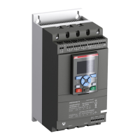
What does 'Phase reversal' mean on my ABB PSTX570 Controller?
- SShannon PaulSep 10, 2025
Phase reversal indicates that the phase sequence is incorrect, leading to current imbalance between the phases. To correct this, change the phase sequence on the line side to (L1-L2-L3). Then, restart the motor and check the main currents and voltage.