20
EN
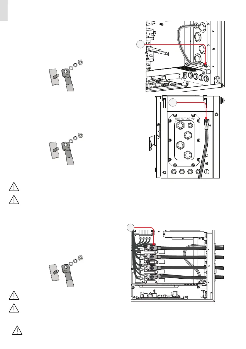
• Depending on the earth connection method (internal (25) or external (10)) follow the procedures described below:
INTERNAL EARTH CONNECTION:
• Pass the protective earth cable trought the proper cable gland on
the AC panel.
• Fix the protective earth cable lug to the protection earth connec-
tion point (int.) (25) using the washers and bolt pre-installed on
the M10 stud, as shown in the following diagram:
1 = cable lug
2 = flat washer
3 = spring washer
4 = M10 nut
1
2
3
25
EXTERNAL EARTH CONNECTION:
• Fix the protective earth cable lug to the protection earth connec-
tion point (ext.) (10) using the washers and bolt pre-installed on
the M8 stud, as shown in the following diagram:
1 = cable lug
2 = flat washer
3 = spring washer
4 = M8 nut
1
2
3
10
The cable lug must be installed with a minimum tightening torque of 21Nm.
Before connecting the inverter to AC or DC sources use a suitable multimeter to test the conductivity of the earth
connections between the protection earth connection point (ext.) (10) and a handles thread (04) on the housing of
power module.
INTERNAL AC CONNECTION:
• Pass the phases cables through the cable glands on the AC
panel.
• Fix the phases and neutral (if required) cable lugs to the AC con-
nection busbars (21), paying attention to the corrispondence of
the phases with the labels, using the washers and the M10 nuts
pre-installed on the busbar as shown in the following diagram:
1 = cable lug
2 = flat washer
3 = spring washer
4 = M10 nut
1
2
3
The minimum recommended cross section for the
phases conductors is 70 mm².
The cable lugs must be installed with a tightening
torque of 25Nm.
21
• Check the tightness of the AC cable glands at the end of the installation.
Make sure the cable glands are properly sealed to ensure to keep IP65 protection degree.
 Loading...


