29
EN
Commissioning via Web User Interface
Commissioning could be carried out via wireless connection to the inverter’s Web User Interface. Initial setup of the system must
therefore be carried out via a tablet, notebook or smartphone with a wireless connection.
• Close the DC disconnect switches (15) to supply the inverter with input voltage from the photovoltaic generator or close the AC
switch downstream of the inverter (and AC disconnect switch (09) for the -S2, -SX2 wiring box version) to supply the inverter with
AC grid voltage. In the pre-commissioning phase the “Alarm” LED keeps quickly flashing, “Power” and “GFI” LEDs are OFF.
• Once powered, the inverter will automatically create a wireless network (approx. 60 seconds after switching-on).
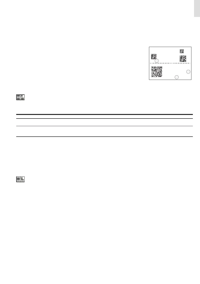
• Enable the wireless connection on the device which is being used for the board setup (tablet,
smartphone or PC) and connect it to the Access Point created by the inverter system: the
name of the wireless network created by the system that the connection should be estab-
lished with, will be: ABB-XX-XX-XX-XX-XX-XX
where “X” is a hex digit of the wireless MAC address (B) (MAC address can be found on the
“Communication Identification Label” placed on the side of the inverter).
• When required enter the PRODUCT KEY (C) (printed on the “Communication Identification la-
bel” and applied during the commissioning phase to the plant documentation) as access
point password (Note that it’s required to digit also the dash “-” characters of the Product Key
in the password field).
SN WLAN: SSSSSSSSSS
PN WLAN: .V2PVKA 53.1
Mac Address:
AA:BB:CC:DD:EE:FF
PK: 0000 - 0000 - 0000- 0000
SN WLAN: SSSSSSSSSS
SN Wiring Box: ZZZZZZZZZZ
Remove and apply on the plant documentation
MAC: AA:BB:CC:DD:EE:FF
B
B
C
• Open an internet browser (recommended browser: Chrome versions from v.55, Firefox versions from v.50) and enter the pre-set
IP address 192.168.117.1 to access the Web User Interface.
• Follow the step-by-step commissioning wizard to complete the commission of the inverter.
For further information regarding the commissioning procedure via Web User Interface, please refer to the user
manual.
• After the commissioning via Web User Interface is completed, the inverter changes the behaviour of the “Power” and “Alarm”
LEDs (08), in relation of the input voltage value:
Input voltage LED Status Description
Vin < Vstart
Power = Flashing
Alarm = OFF
The input voltage is not sufficient to enable connection to the grid.
Vin > Vstart
Power = Flashing
Alarm = ON
The input voltage is sufficient to enable connection to the grid: the
inverter waits for the grid voltage to be present to make the con-
nection to the grid.
• Depending of the supply source used to complete the installation wizard steps, close the disconnect switch of missing voltage
sources: In case of missing AC source close the AC switch downstream of the inverter (and AC disconnect switch (09) for the -S2,
-SX2 wiring box version); In case of missing DC source close the DC disconnect switches (15).
• When the input voltage is sufficient to allow the connection to the grid, the inverter will check the grid voltage, measure the isola-
tion resistance of the photovoltaic field with respect to earth and performs other auto-diagnostic checks. During the preliminary
checks on the parallel connection with the grid, the “Power” LED keeps flashing, the “Alarm” and “GFI” LEDs are OFF. The inverter
will ONLY connect to the grid if all parameters fall within the ranges foreseen by current regulations.
• If the outcome of the preliminary checks to grid synchronization are positive, the inverter connects and starts to export power to
the grid. The “Power” LED remains fixed on while the “Alarm” and “GFI” LEDs are OFF.
To address any problems that may occur during the initial stages of operation of the system and to ensure the inverter remains
fully functional, you are advised to check for any firmware updates in the download area of the website www.abb.com/solarinver-
ters or at https://registration.abbsolarinverters.com (instructions for registering on the website and updating the firmware are
given on the user manual).
 Loading...


