101
Status of the
protection
elements
Channel State of element
(R)
Recorded
functions (R)
Value
Trip of element
49/38-1
0,2 O19 O79 0/1
Alarm of element
49/38-2
0,2 O20 O80 0/1
Trip of element
49/38-2
0,2 O21 O81 0/1
CBFAIL trip 0,3 O22 O82 0/1
Table 5.1.15.-10 Outputs
Operation of
output
contact
Channel State of
output (R, W,
P)
Recorded
functions (R)
Value
Output PO1 0,2 O41 O101 0/1
Output PO2 0,2 O42 O102 0/1
Output PO3
a)
0,2 O43 O103 0/1
b)
Output SO1 0,2 O44 O104 0/1
Output SO2 0,2 O45 O105 0/1
Output PO3
(restart
disable)
c)
0,2 O46 - 0/1
b)
Enabling
activation of
output
contacts PO1,
PO2, PO3,
SO1, and SO2
via the SPA
bus
0,2 O51 - 0/1
a)
State of output when the pickup, trip and alarm signals from the protection elements, the motor start-up
signal and the external trip signal have been routed to PO3 (SGR3/1...19=1), provided that SGF1/7=1.
b)
Either O43/O103 or O46 is to be used at a time.
c)
State of output when the trip lockout function is in use.
Parameters O41...O46 and O51 control the physical output contacts
which can be connected to circuit breakers, for instance.
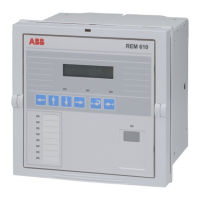
Motor Protection Relay
Technical Reference Manual - ANSI Version
REM 610REM 610
1MRS755537

 Loading...