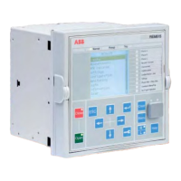
ABB 10
1MAC251744 -PG Rev. A
Issued: 03.01.2010
Motor Protection
REM615 ANSI
Product Version 2.0
6. Control
e relay o ers status and control of one circuit
breaker with dedicated push-buttons on the front
panel local human machine interface (LHMI) for
opening and closing of that breaker. Flexible remote
breaker control of select-before-trip (SBO) or direct
trip is also available with each of the supported
DNP3.0 Level 2+, Modbus and IEC 61850
communication protocols. Interlocking schemes
required by the application are con gured with the
signal matrix tool in PCM600 by the application are
con gured with the Signal Matrix Tool (SMT) of the
REM615 user tool PCM600.
7. Measurements
e relay continuously measures the phase currents,
the sequence components of the currents and the
residual current. If the relay includes the ground
ct option, it also measures the ground current, IG.
In addition, the relay calculates the demand phase
currents over a user-selectable pre-set time frame, the
thermal overload of the protected object, and the
phase unbalance value as a ratio between the negative
sequence and positive sequence currents. With the
VT option, phase, ground and sequence voltage
measurements plus power, energy and power factor
measurements are included.
e values measured can be accessed locally via the
user interface on the relay front panel or remotely via
the communication interface of the relay. e values
can also be accessed locally or remotely using the web-
browser based user interface.
8. Digital fault recorder
e relay is provided with a digital fault recorder
(DFR) featuring up to four analog and 64 binary
signal channels. e analog channels record either the
waveform or the trend of the currents measured.
e analog channels can be set to trigger the recording
function when the measured value falls below or
exceeds the set values. e binary signal channels can
be set to start a recording on the rising or the falling
edge of the binary signal or both.
By default, the binary channels are set to record
external or internal relay signals, e.g. the pickup or
trip signals of the relay stages, or external blocking or
control signals. Binary relay signals such as a protection
pickup or trip signal, or an external relay control signal
over a binary input can be set to trigger the recording.
With the VT option, phase and ground voltage
waveforms would be available for inclusion in each
digital recording.
9. Events recorder
e IED includes a sequence of events recorder (SER)
that logs important event activity. To collect sequence-
of-events (SER) information, the relay incorporates
a memory with a capacity of storing 100 event codes
with associated time stamps with associated date and
time stamps.. e event log facilitates detailed pre- and
post-fault analyses of feeder faults and disturbances.
e SER information can be accessed locally via the
user interface on the relay front panel or remotely
via the communication interface of the relay. e
information can further be accessed, either locally or
remotely, using the web-browser based user interface.
10. Fault recorder
e relay has the capacity to store the records of 100
fault events. e records enable the user to analyze
the four most recent power system events. Each
record includes the current values, the Pickup times
of the protection blocks, time stamp, etc. e fault
recording can be triggered by the pickup signal or
the trip signal of a protection block, or by both. e
available measurement modes include DFT, RMS
and peak-to-peak. In addition, the maximum demand
phase currents with date and time stamp are separately
stored as recorded data. All 100 records are remotely
retrievable via DNP3.0 Level 2+ and Modbus
protocols and the four most recent fault records are
retrievable and viewable using the front panel HMI,
WMHI and PCM600 interfaces using the front panel
HMI, web-based WHMI and PCM600 interfaces.

 Loading...