ABB 34
1MAC251744 -PG Rev. A
Issued: 03.01.2010
Motor Protection
REM615 ANSI
Product Version 2.0
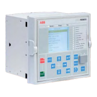
Fig. 7: Flush mounting Fig. 8: Semi-fl ush mounting Fig. 9: Semi-fl ush with a
25º tilt
21. Mounting methods
By means of appropriate mounting accessories the
standard relay case for the 615 series relays can be ush
mounted, semi- ush mounted or wall mounted. e
ush mounted and wall mounted relay cases can also
be mounted in a tilted position (25°) using special
accessories.
Further, the relays can be mounted in any standard 19”
instrument cabinet by means of 19” mounting panels
available with cut-outs for one or two relays.
For the routine testing purposes, the relay cases can be
equipped with Flexitest (FT) test switches, type FT-1
or FT-19R, which can be mounted side by side or below
the relay cases.
Mounting methods:
• Flush mounting
• Semi- ush mounting
• Semi- ush mounting in a 25° tilt
• Rack mounting
• Wall mounting
• Mounting to a 19” equipment frame
• Mounting with Flexitest (FT) test switches to a
19”rack
Panel cut-out for ush mounting:
• Height: 6.36” ± 0.04” (161.5±1 mm)
• Width: 6.52” ± 0.04” ( 165.5±1 mm)
22. Relay case and
drawout unit
For safety reasons, the relay cases are provided with
automatically operating contacts for short-circuiting the
CT secondary circuits when a relay unit is withdrawn
from its case. e relay case is further provided with a
mechanical coding system preventing current measuring
relay units from being inserted into a relay case for a
voltage measuring relay unit and vice versa, i.e. the relay
cases are assigned to a certain type of relay draw-out unit.

 Loading...