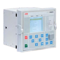
ABB 12
1MAC251744 -PG Rev. A
Issued: 03.01.2010
Motor Protection
REM615 ANSI
Product Version 2.0
16. Access control
To protect the IED from unauthorized access and to
maintain information integrity, the IED is provided
with a four-level, role-based authentication system with
administrator programmable individual passwords
for the viewer, operator, engineer and administrator
level. e access control applies to the frontpanel user
interface, the web-browser based user interface and the
PCM600 tool.
17. Inputs and outputs
In both con gurations available, the REM615 is
equipped with three-phase and ground ct analog inputs
standard for fundamental motor protection including
thermal overload, motor start, locked rotor and stall
protection, negative sequence current, phase reversal,
loss of load and excessive starts protection plus motor
start-time supervision and emergency start capability.
Maximizing exibility of application, the phase and
ground ct secondary ratings are independently user
programmable to 5 A or 1 A. e con guration having
the voltage inputs (vt) option allow for independent
user programmable vt secondary rating for the three-
phase and ground VT analog inputs.
e binary input turn-on thresholds are programmable
from 18…176 V DC by adjusting the relay’s param-
eter settings. All binary input and output contacts are
freely programmable with the signal matrix tool in the
REM615 PCM600 so ware user tool. Relay analog
input and binary input/output overview:
• ree phase-current and ground ct inputs
• Optional three-phase and ground vt inputs
• Twelve binary inputs standard, 18 optional, without vt
inputs
• Twelve binary inputs standard with vt inputs
• Two NO outputs with trip circuit monitoring
• ree NO outputs
• One Form C output
• One Form C self-check alarm output
• Ten binary outputs standard, optional 13 binary out-
puts without vt inputs
Functional application, analog inputs (standard
con guration) order code
Analog inputs
Binary I/O
order code
Binary inputs/outputs
CT VT BI BO
AAA 4 0 AA 12 10
AAA 4 0 AB 18
1)
13
1)
CCA 4 5
1) ,2)
CA 16 10
1)
Optional
2)
One of the ve inputs is reserved for future applications
Table 4. Inputs and outputs (I/O) overview

 Loading...