Operation mode 2I
0
· cosφ
GUID-6C7CFB2B-2B83-4E2C-80B9-318432DDAE1C v2
Procedure
1. Set the polarizing voltage to 1.2 · UNRel> and set the phase angle between
voltage and current to the set characteristic angle (RCADir). Note that the
current shall lag the voltage.
Take setting RCAComp into consideration if not equal to 0.
2. Inject current until the function picks up, and make sure that the operate
current of the set directional element is equal to the INcosPhi> setting.
The I Dir (2I
0
· cosφ) function activates the START and STDIRIN output.
3. Assume that φ is the phase angle between injected voltage (-2U
0
) and current
(2I
0
) i.e. φ = RCADir-φ. Change φ to for example 45 degrees. Increase the
injected current until the function operates.
4. Compare the result with the set value and make sure that the new injected 2I
0
· cos φ is equal to the setting INcosPhi>.
Take the set characteristic into consideration, see Figure
24 and Figure 25.
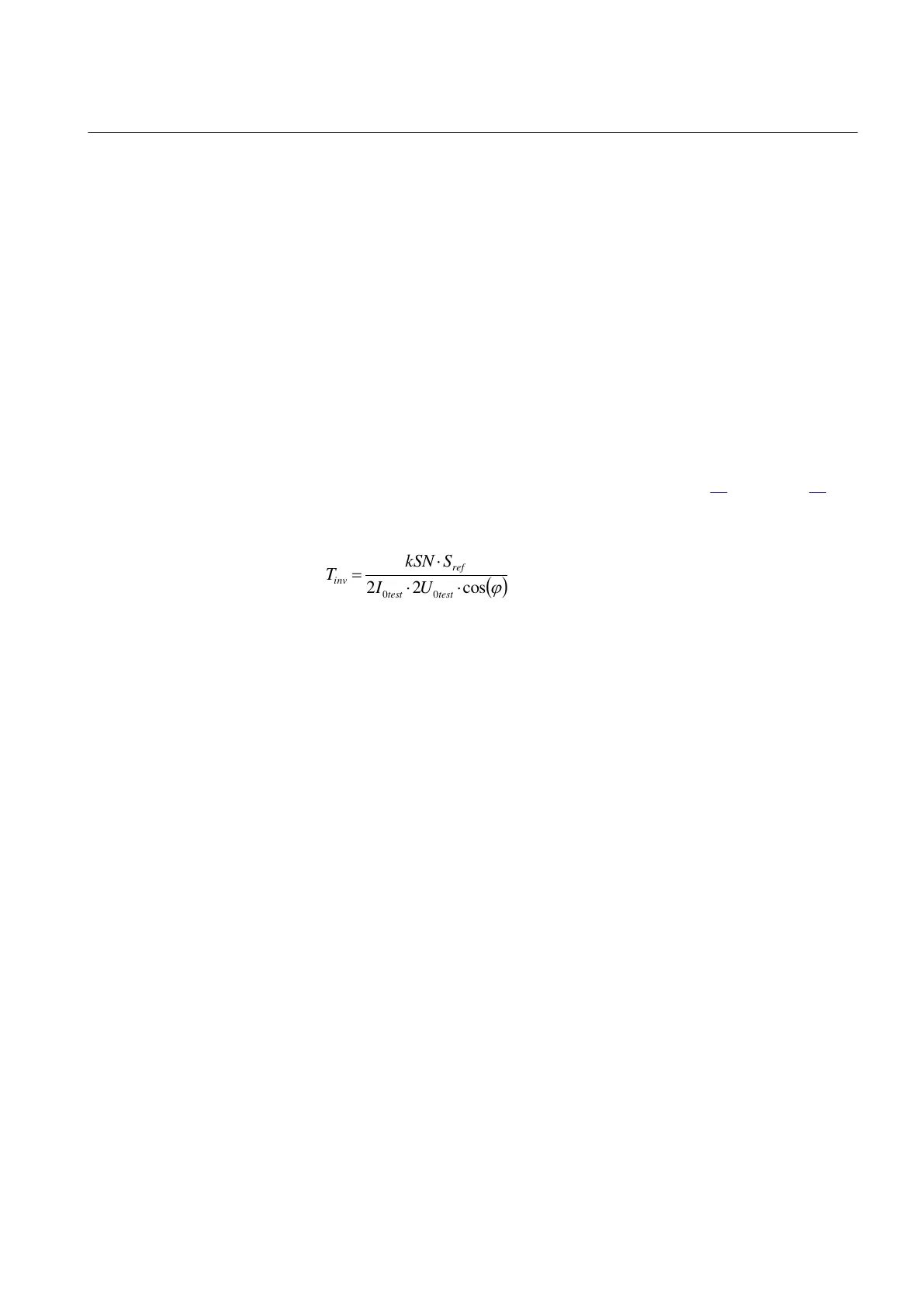
5. Measure the operate time of the timer by injecting a current two times the set
INcosPhi> value and the polarizing voltage 1.2 · UNRel>.
cos22
00
testtest
ref
inv
UI
SkSN
T
IECEQUATION234 V1 EN-US (Equation 3)
6. Compare the result with the expected value.
The expected value depends on whether definite or inverse time was selected.
7. Set the polarizing voltage to zero and increase until the boolean output signal
UNREL is activated, which is visible in the application configuration in
PCM600 when the IED is in online mode and also on the IED HMI under
test. Compare the voltage with the set value UNRel> .
8. Continue to test another function or complete the test by setting the test mode
to Off.
1MRK 506 377-UEN C Section 10
Testing functionality by secondary injection
Railway application RER670 2.2 IEC 109
Commissioning manual