10 CI/SM500F–EN Rev. A
Power supply connections
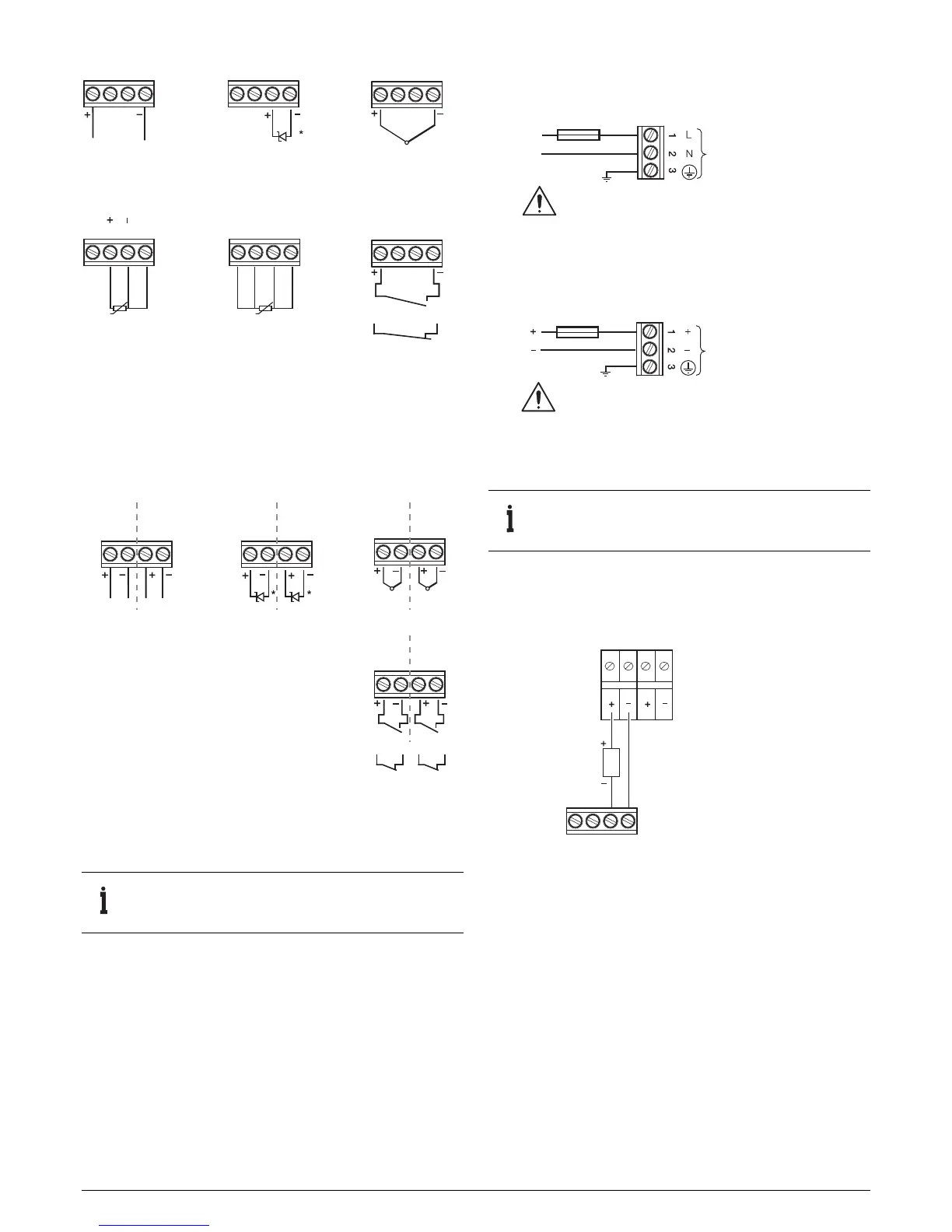
Transmitter power supply module
One transmitter power supply module can be fitted in position D
to provide a nominal 24 V supply capable of driving two, 2-wire
transmitters.
Fig. 8 Single analog / digital input connections
Fig. 9 Dual analog / digital input connections
IMPORTANT (NOTE) Tighten all analog / digital input
terminal screws to a torque of 0.5 Nm (4.5 lbf.in).
1 2 3 4
1 2 3 41 2 3 4
1 2 3 4
1 2 3 4
1 2 3 4
*In the powered-down condition the current input is open circuit.
In order to maintain a current loop when the recorder is powered
down, fit a zener diode (BZX79 – B/C2V4) to the input as shown.
Voltage Current Thermocouple
3-lead RTD 4-lead RTD Digital input
(volt-free or 24 V)
Each lead must be of equal
resistance and less than 10
Logic state inactive
Logic state active
Third lead
White
Red
Red
1 2 3 41 2 3 4 1 2 3 4
1 2 3 4
*In the powered-down condition the current
input is open circuit. In order to maintain a
current loop when the recorder is powered
down, fit a zener diode (BZX79 – B/C2V4) to
the input as shown.
Voltage Current Thermocouple
Input 1 Input 2
Digital input
(volt-free or 24 V)
Logic state inactive
Logic state active
Input 1 Input 2 Input 1 Input 2
Input 1 Input 2
Fig. 10 Power supply connections
IMPORTANT (NOTE) Tighten power supply terminal
screws to a torque of 0.8 Nm (7 lbf.in).
Fig. 11 Power supply connections
A – AC supply
Warning. Use fuse rating 315 mA (max.) type T
100 V min. to 240 V max,
50 / 60 Hz
B – DC supply
Fuse
305 mA, type T
Line
Neutral
Fuse
1.5 A, type T
10 V min. to 36 V max, DC
Warning. Use fuse rating 1.5 A (max.) type T
2-wire transmitter power supply
(24V DC, 22mA max.)
Analog input

 Loading...


