12 S P I R I T
IT
F L O W- X INS T R U C T I O N M A N U A L | I M/ F L O W X - EN
4 Getting started
This chapter provides a short overview of considerations to be
made in selecting the appropriate Spirit
IT
Flow-X products.
Location
The Spirit
IT
Flow-X modules are designed to operate in a
temperature range of 0-60 °C (32-140°F) humidity may be up to
90%, non-condensating. In practice, the modules are usually
mounted in racks in a controlled environment such as a control
room, rack room or auxiliary room, or an analyzer house.
Caution
The Spirit
IT
Flow-X is neither intrinsically safe nor explosion-
proof and can therefore only be used in a designated non-
hazardous (safe) area.
For other devices always refer to documentation supplied by the
manufacturer for details of installation in a hazardous area.
If connected to a device that resides in a hazardous area, it may
be required to interpose safety barriers or galvanic isolators
between the device and the Spirit
IT
Flow-X flow computer. Refer
to the device documentation for adequate information.
Capabilities
The Spirit
IT
Flow-X supports an extensive list of International
standard calculations for Natural gas, hydrocarbon liquids, and
other applications: For example:
AGA3, AGA5, AGA7, AGA8, AGA10
API chapters 11.1, 11.2, and 21.1, API 2540, API 1952 tables
ISO 5167 (all editions), ISO 6976 (all editions)
NX19, SGERG, PTZ calculations
GPA 2172 / TP15 / TP16 / TP25 / TP27
ASME 1967 (IFC-1967) steam tables, IAPWS-IF97 steam density
GERG 2008
Number of modules
Basically one module is needed for each flow meter. Additional
modules may be needed for station and /or proving
functionality.
A Flow-X/P contains an extra module (Module 0) that controls
the touch screen and handles station and /or proving
functionality (if applicable).
The Flow-X/C is a compact version and similar to a Flow-X/P
with one module. This module is integrated in the enclosure of
the Flow-X/C.
An overview of the available I/O per module may be found in
Chapter 7 – Technical Specifications.
Station functionality (calculating station totals and / or handling
station densitometers, gas chromatographs, BS&W analyzers
etc.) and / or proving functionality may also be calculated in any
module in the same enclosure, including the Flow-X/P Panel
display module.
Special consideration applies to serial ports. Every module has 2
serial ports. If more ports are required, the Flow-X/P may be
considered as it has 3 extra serial ports. Alternatively, a second
module may be added in a Flow-X/R (rack) enclosure to provide
more serial communication ports.
Redundancy
If, for increased availability, a redundant solution is required, 2
modules per stream may be used.
To obtain maximum availability, two identical Spirit
IT
Flow-X
enclosures can be used that operate in redundancy mode.
All modules have integrated support for dual 24V power supply.
Fast Data exchange
Modules placed in a Flow-X/P (Panel) or Flow-X/R (Rack)
enclosure are capable of fast data exchange with the modules
next to it, over the Ethernet. This is the so-called Multi-Module
Mode. Examples are one module communicating to a Gas
Chromatograph and making this data available to 4 other
modules, and additionally serving as a Modbus Slave to one
central DCS connection. Each Module is capable of using the
data from other modules as if it exists in its own data space. For
this purpose the Flow-X/P includes two dedicated Ethernet
switches. As an alternative it is possible to set up a Modbus
TCP/IP link using Ethernet for data exchange between modules.
Display requirements
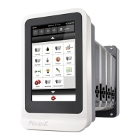
Obviously the Flow-X/P (Panel) and Flow-X/C (Compact) flow
computers have the best display features. The touch screen has
the largest display area available on the flow computer market
and allows for effective and user-friendly data display and
navigation through pages. Its multi-language-support is unique
and includes non-western fonts.
This display feature is not always required. Each individual
module is equipped with a local black and white graphical
display, allowing for data display and parameter setting at the
module itself. The display supports 4 to 8 lines for data and/or
parameters. This feature enables the stand-alone use of the flow
modules, including in fiscal applications.
Apart from these physical displays, each module incorporates a
web server, allowing display pages to be accessed through a
standard web browser over Ethernet.
Power supply
All models require 24 VDC and support redundant power supply.
 Loading...


