30 SPIR I T
IT
F L O W- X INS T R U C T I O N M A N U A L | I M/ F L O W X - EN
Remote prover IO
Ball prover / Compact prover
Connect the flow pulse signals to the corresponding run
modules
Connect the detector signals to each run module
Connect all applicable prove signals (except the detector
signals) to the remote prover IO module:
– prover pressure(s)
– prover temperature(s)
– prover densitometer
– 4-way valve commands and statuses
– prover commands and statuses
Figure 6-38: Single stream flow computers using a common prover
IO server module.
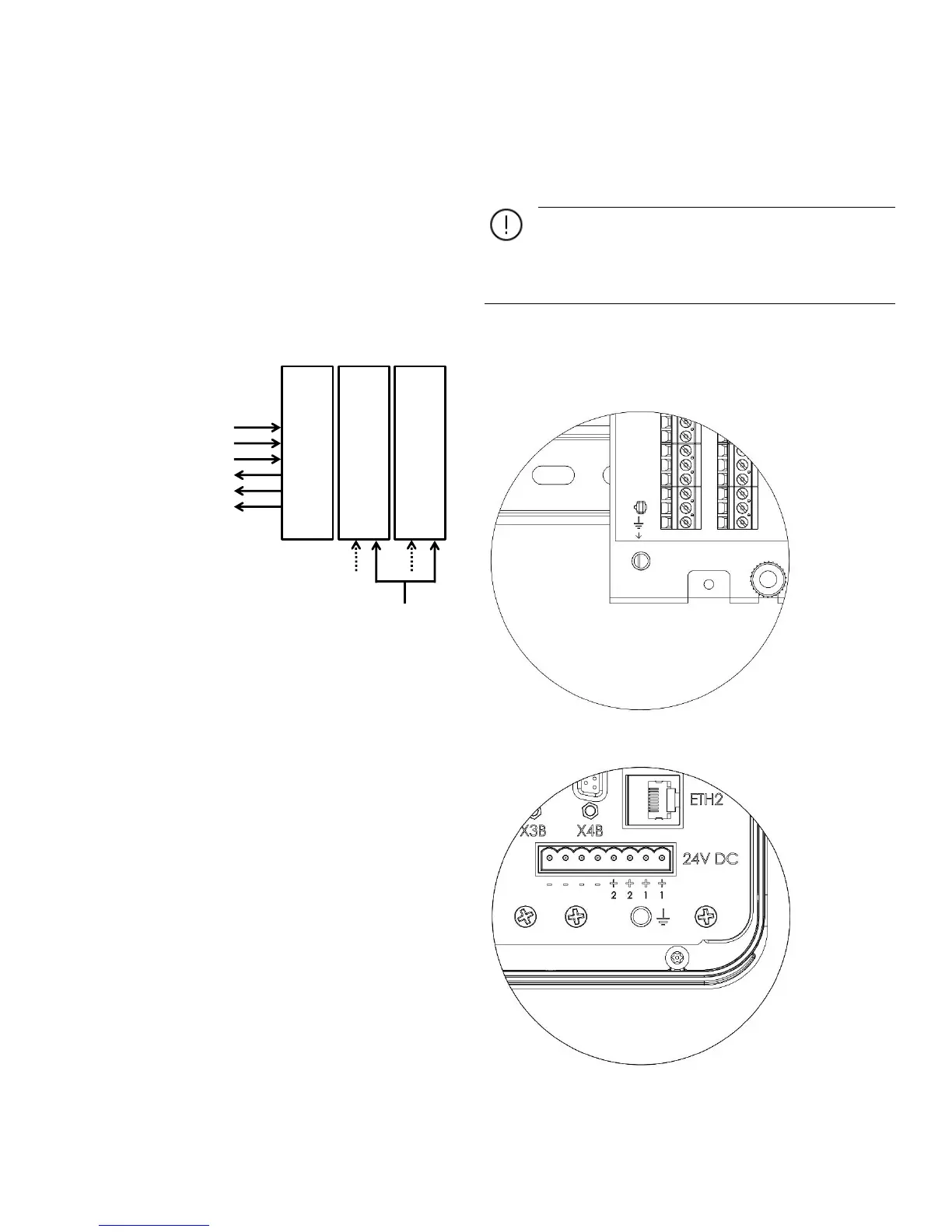
Earth ground connection
The chassis must be connected to a good earth ground to
prevent human contact with dangerous voltages and to
minimize the effects of electrical transients.
For the correct operation of the device it is important to
verify that there is no (significant) difference between
the voltage levels of the signal ground (0 V of the power supply)
and the earth ground.
The following pictures show the location of the threaded stud
for the connection of the earth ground wire for the different
Spirit
IT
Flow-X enclosures.
Figure 6-39 Flow-X/S earth ground connection
Figure 6-40 Flow-X/P earth ground connection

 Loading...


