S P I R I T
IT
F L O W- X INS T R U C T I O N M A N U A L | I M/ F L O W X - EN 25
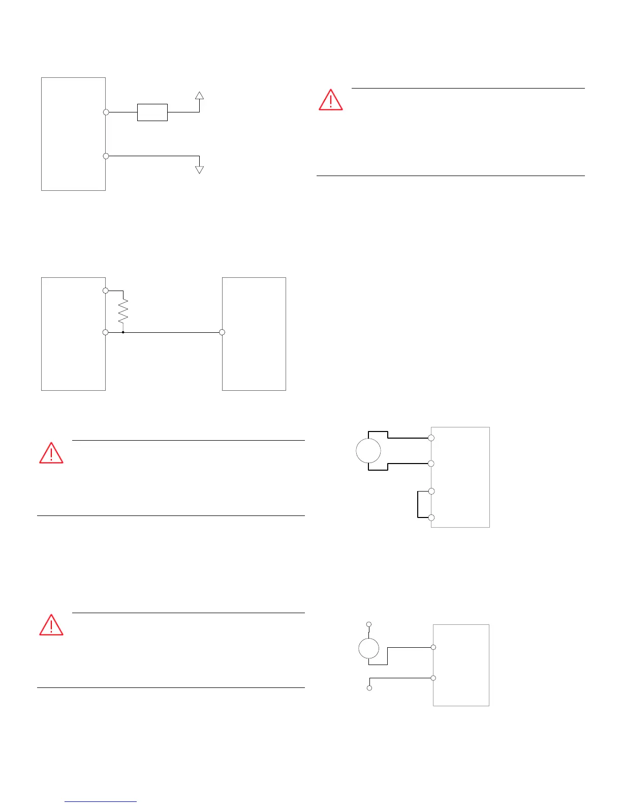
Figure 6-16 Externally powered digital output
To connect a digital output of one Spirit
IT
Flow-X flow computer
to a digital input of another Spirit
IT
Flow-X flow computer an
external resistor is required.
Figure 6-17 Connecting a digital output to a digital input
Pulse outputs
When connected to a device that resides in a hazardous
area, safety barriers or galvanic isolators may be
required to be interposed between the device and the Spirit
IT
Flow-X flow computer. Refer to the device documentation for
adequate information.
Each flow module has pulse outputs available. These outputs can
be used to increase external flow counters. The complete
definition can be done by the Spirit
IT
Flow-Xpress configuration
software.
Prover bus output
When connected to a device that resides in a hazardous
area, safety barriers or galvanic isolators may be
required to be interposed between the device and the Spirit
IT
Flow-X flow computer. Refer to the device documentation for
adequate information.
Each flow module has a prover bus output. The prover bus
output can be configured using the Spirit
IT
Flow-Xpress
configuration software.
Analog signals
Analog inputs
When connected to a device that resides in a hazardous
area, safety barriers or galvanic isolators may be
required to be interposed between the device and the Spirit
IT
Flow-X flow computer. Below paragraph contains application
examples with barriers. Always refer to the device
documentation for adequate information.
Each flow module provides 6 analog inputs. Each analog input is
software configurable as 4-20 mA, 0-20 mA, 1-5 Volt or 0-5 Volt
input.
For each flow module the first 4 analog inputs can also be used
as HART inputs.
The analog input circuits are floating in relation to the other type
of I/O, with a single common ground shared between the analog
inputs of the same flow module.
When the analog input channel is used as a mA input, the internal
resistor of 250 Ω is activated.
When the loop is internally powered through one of the several
'24 Vdc out' terminals of the Spirit
IT
Flow-X flow computer, the
common analog input ground must be referenced to the same
reference ground as the power supply as shown below.
Figure 6-18 Internally powered mA input
When the mA loop is externally powered then the grounding
method depends on whether the application uses an isolated
power supply and isolated grounding for analog inputs, refer to
section 'Ground wiring'.
Figure 6-19 Externally powered mA input
When the analog input is configured for measuring 0 to 5 Vdc or
1 to 5 Vdc the internal resistor is disconnected and the voltage

 Loading...


