35
—
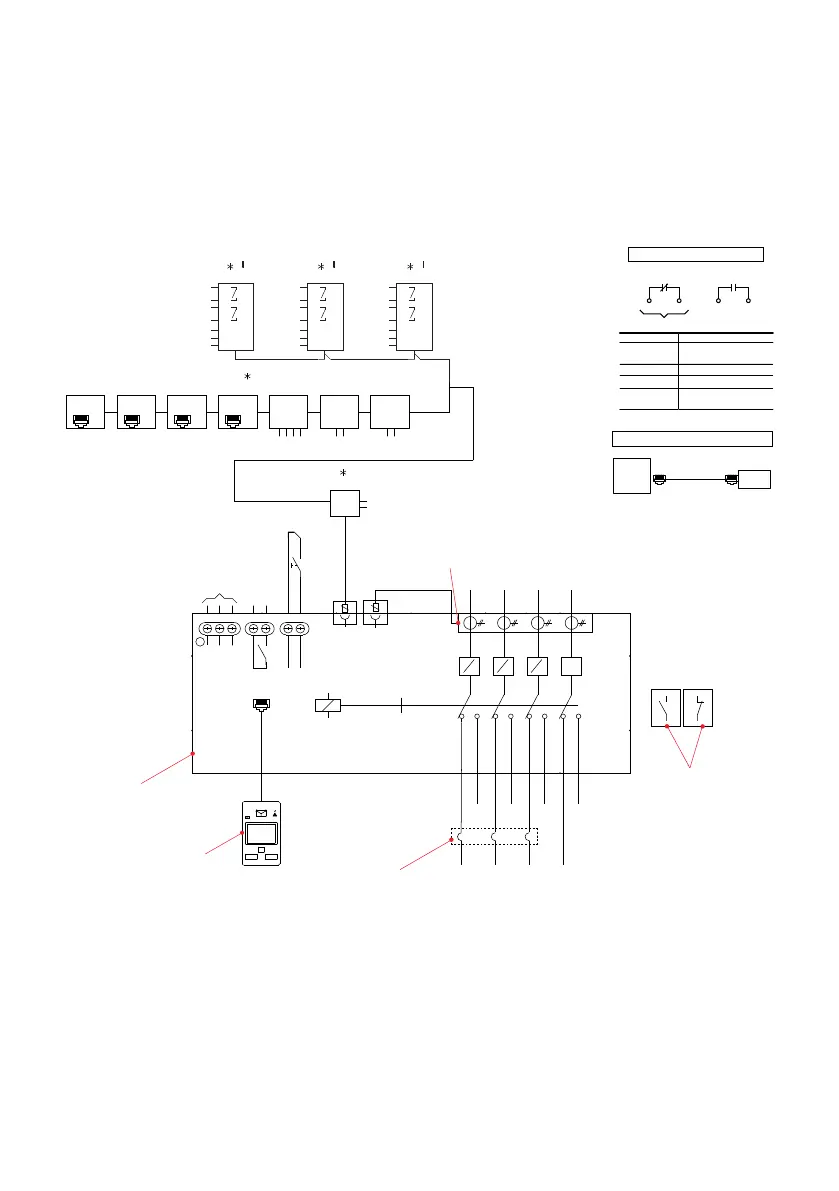
ZTGSE 30-1200A Delayed transition
—
Fig. 15 ZTSSE
Please refer 77A-2006 for further details
G
C O1 C I1
OA1G10 OA3G01
OA_
S1: 2+2 pcs
S2: 2+2 pcs
6
1 2 3 5 6 12 13
A
L1
B
L2
C
L3
N
K1 +
K2 -
Modbus RTU
W1 (A)
W2 (B)
W6 (A)
W5 (B)
Profibus DPDeviceNet
V-
W8 (L)
W7 (H)
V+
Modbus TCP
W9
RJ45
Profinet
W10
RJ45RJ45
EtherNet/IP
W11
RJ45
IEC 61850
W12
OX_30...250: 3 pcs
OX_260...1600: 4 pcs
K14
K13
O 12
K12
O 11
K11
H12
HC1 I 12
H11 I 11
K24
K23
O 22
K22
O 21
K21
H22
HC2 I 22
H21 I 21
O 31
O 32
K31
K32
K33
K34
H31
H32
HC3
I 31
I 32
RJ45
13
14
11
12
S2 S2 S2
S1
S2
Ekip 2K-1Ekip 2K-2Ekip 2K-3
L2 L3 N
L1
14
OXCT_
1. COMMON
2. CLOSES TO START
3. OPENS TO START
S1
S1 S1
Notes:
1. ATS shown in source 1 position with power available.
2. Refer to operation and maintenance manual to configure the options.
3. # of N.O. contacts on power panel will be different based on the switch amperage.
Review the product brochure for the details.
ROGOWSKI
COILS
LOAD
LUG
POWER
PANEL
CONTROLLER
(MOUNTED ON THE
CABINET FLOOR)
CIRCUIT BREAKER
SOURCE
LUG
AUX CONTACTS
(OPTIONAL)
LOCATE RIGHT
SIDE OF PANEL
ENGINE START
CONTACTS
E
-Q1
OXA_
OXEA1
Ekip COM_
RJ45 RJ45
CUSTOMER CONNECTIONS
ENGINE START
1 2
1 3
E
CONTACT RATING
E 5 AMP @ 240 VAC
5 AMP @ 30 VAC
OA1G10 (N.O.) 6 AMP @ 125, 250 VAC
OA3G01 (N.C.) 6 AMP @ 125, 250 VAC
Ekip Module 4 AMP @ 240 VAC
(2K- 1, 2, 3) 2 AMP @ 30 VAC
INTERCONNECT PLUG DIAGRAM
ATS
POWER
PANEL
HMI
AUTO
S1 S2
LOAD
l ll
!
 Loading...