43
1. ABB Zenith Service entrance equip-
ment are mounted onto a wooden
pallet using bolts and nuts. Please
remove the bolts and nuts prior to
lifting.
2. ABB Zenith Service entrance equip-
ment enclosures have the provisions
for lifting through the standard over-
head lifting device.
3. Wall mount unit need to be listed with
fork lift from bottom or through suit-
able lifting straps. Engage the lifting
hooks and adjust lifting positions such
that the hooks are pointing outward.
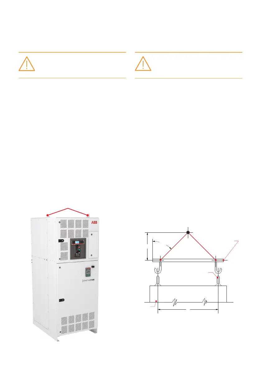
Lifting eyelets
—
Fig. 18 Automatic Transfer Switch Enclosed Assembly
Lifting locations
Note: When lifting the switch using a spreader bar,
height H must be equal to half of distance D
—
Fig. 19 Recommended Lifting Angle
4. Refer to Table 12 for the weight infor-
mation, or the dimensional drawing
for the center of gravity (denoted as
CG), weight information, lifting provi-
sion, and anchoring hole pattern on
lower mount C-channels.
5. While lifting the unit using lifting
chains, it is recommended to maintain
6. Refer to Fig. 18 for lifting provisions
on the enclosure top.
7. ABB Zenith Service entrance equip-
ment uni ts sh ould b e lif te d usin g prop el y-
rated lifting devices.
Warning:
Lifting hazard
Failure to follow these instructions could result
in death or serious injury.
Lifting Guidelines for Service Entrance
Automatic Transfer Switches
45°
Spreader bar
Lifting eyes
Cabinet
H
D
Avertissement:
Risque de levage
Le non-respect de ces instructions peut
entraîner la mort ou des blessures graves.