TPU2000/2000R Modbus/Modbus Plus Automation Guide
157
The Breaker Failed to Trip time register is configured a number representing the number of cycles which the
breaker shall trip. The range is a number from 5 to 60. The amount of time for breaker failed to trip is, of course
dependent upon whether the relay is a 50 or 60 Hz model.
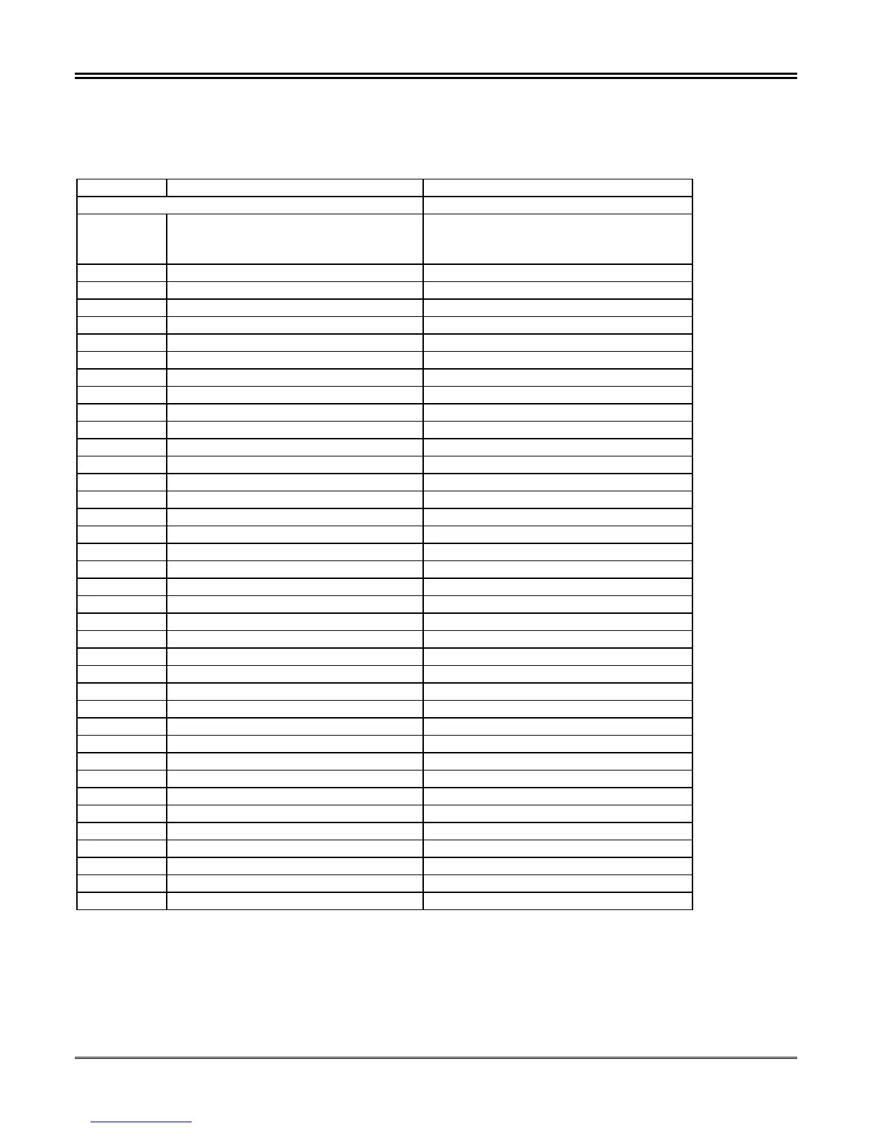
Table 5-52. TPU2000/TPU2000R Bit Control Function Definitions
Register Item Description
GROUP VI
41452 Execute Register
0 = No Action
1 = Execute
Unsigned (16 Bits)
41453 Password ASCII – 2 Characters Leftmost Digits
41454 Password ASCII – 2 Characters Rightmost Digits
41455 Spare
41456 Pulse Physical Output Change Mask Unsigned (16 Bits)
Bit 0 Trip(lsb) 1 = Pulse Output 0 = No Control
Bit 1 Output 1 (Terminals 28,27) 1 = Pulse Output 0 = No Control
Bit 2 Output 2 (Terminal 26,25) 1 = Pulse Output 0 = No Control
Bit 3 Output 3 (Terminal 24,23) 1 = Pulse Output 0 = No Control
Bit 4 Output 4 (Terminal 22,21) 1 = Pulse Output 0 = No Control
Bit 5 Output 5 (Terminal 19,20) 1 = Pulse Output 0 = No Control
Bit 6 Output 6 (Terminals 17,18) 1 = Pulse Output 0 = No Control
Bit 7 Output 7 (TPU2000 ONLY) 1 = Pulse Output 0 = No Control
Bit 8 Reserved
Bit 9 Reserved
Bit 10 Reserved
Bit 11 Reserved
Bit 12 Reserved
Bit 13 Reserved
Bit 14 Reserved
Bit 15 Reserved (msb)
41457 Pulse Physical Output Change Mask Unsigned (16 Bits)
Bit 0 Trip(lsb) 1 = Pulse Output 0 = No Control
Bit 1 Output 1 (Terminals 28,27) 1 = Pulse Output 0 = No Control
Bit 2 Output 2 (Terminal 26,25) 1 = Pulse Output 0 = No Control
Bit 3 Output 3 (Terminal 24,23) 1 = Pulse Output 0 = No Control
Bit 4 Output 4 (Terminal 22 21) 1 = Pulse Output 0 = No Control
Bit 5 Output 5 (Terminal 19,20) 1 = Pulse Output 0 = No Control
Bit 6 Output 6 (Terminal 17,18) 1 = Pulse Output 0 = No Control
Bit 7 Output 7 (TPU2000 ONLY) 1 = Pulse Output 0 = No Control
Bit 8 Reserved
Bit 9 Reserved
Bit 10 Reserved
Bit 11 Reserved
Bit 12 Reserved
Bit 13 Reserved
Bit 14 Reserved
Bit 15 Reserved (msb)
Group IV functions operate as follows and detailed in Example 6:
Register 41456 = Pulse Physical Output Mask - Selects Control for the Function Specified.
Register 41457 = Confirm Pulse Physical Output Mask (Copy of Register 41456).