TPU2000/2000R Modbus/Modbus Plus/ Modbus TCP/IP Automation Guide
18
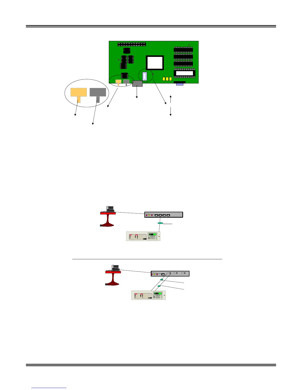
Move Switch To
Card Edge to Enable Fiber Interface
Move Switch Away From Card Edge
to Enable Copper Interface.
Fiber Optic Connectors
10 BASE FL
Copper Connector
10 Base T
TX RX
Transmit
Connector
Receive
Connector
Figure 3-10. Connection Diagram for Copper/Fiber Interfaces
Ethernet connectivity is based upon a star topology connection. The Ethernet card operates with an Ethernet Hub
or Switch to effectuate operation. The topology diagrams are illustrated in Figure 3-11 of this document
illustrating the topology of the device.
If an Ethernet switch is used, reference the manufacturer’s documentation for setup of the device.
E
C
NORMAL
FAIL
PICKUP
RECLOSER OUT
SYSTEM RESET
TIME
INSTANTANEOUS
FREQUENCY
NEGATIVE SEQUENCE
TARGET RESET
STATUS TARGETS
A
B
C
N
DPU
2000 R
Network
Partne r
V1.0
HUB/SWITCH
CAT 5 CABLE - Copper
E
C
NORMAL
FAIL
PICKUP
RECLOS ER OUT
SYSTE M RE SET
TIME
INSTANTANEOUS
FREQUENCY
NEGATIVE SEQU ENCE
TARGET RESET
STATU S TARGETS
A
B
C
N
DPU
2000R
Network
Partne r
V1.0
HUB/SWITCH
Transmit Fiber
Receive Fiber
COPPER ETHERNET
FIBER OPTIC
ETHERNET
Figure 3-11. Typical Hub/Switch Connection Using Fiber or Copper Ethernet
Fiber Optic Specifications
THE COPPER PORT IS NOT ISOLATED. IT IS ONLY RECOMMENDED THAT THIS PORT BE USED FOR
LABORATORY USES AND IN CASES WHERE ISOLATION OF THE RELAY IS NOT AN ISSUE.