6 TZIDC, TZIDC-200 DIGITAL POSITIONER | COI/TZIDC/TZIDC-200-EN REV. B
2 Operation
Safety instructions
Risk of injury due to incorrect parameter values!
Incorrect parameter values can cause the valve to move
unexpectedly. This can lead to process failures and result in
injuries.
• Before recommissioning a positioner that was previously
in use at another location, always reset the device to its
factory settings.
• Never start automatic adjustment before restoring the
If there is a chance that safe operation is no longer possible,
take the device out of operation and secure it against
unintended startup.
Parameterization of the device
The LCD display features operating buttons which enable the
device to be operated with the housing cover open.
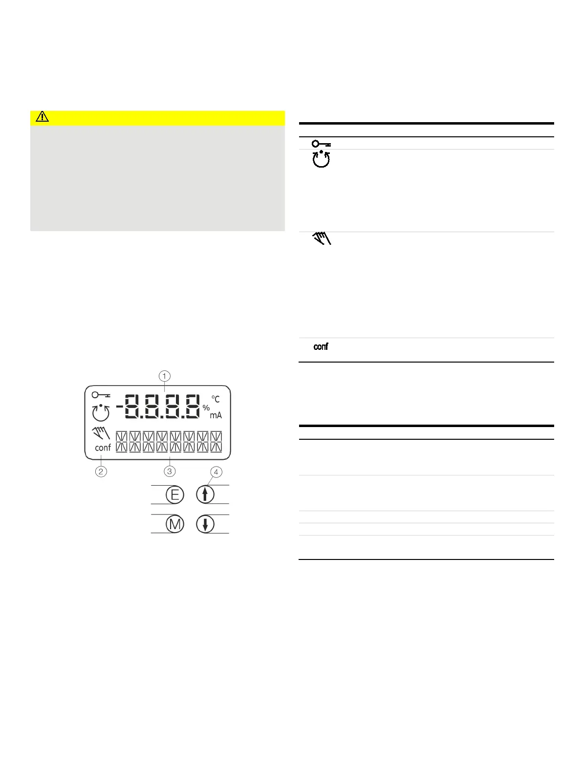
Menu navigation
Value display with unit
Symbol display
Designator display
Operating buttons for menu
navigation
Figure 1: LCD display with operating buttons
Value display with unit
This 7-segment display with four digits indicates parameter
values or parameter reference numbers. For values, the physical
unit (°C, %, mA) is also displayed.
Designator display
This 14-segment display with eight digits indicates the
designators of the parameters with their status, of the
parameter groups, and of the operating modes.
Description of symbols
Operation or access is restricted.
The symbol is displayed when the positioner is in operating
mode 1.0
CTRL_ADP (adaptive control) or 1.1 CTRL_FIX (fixed
control) at operating level. On the configuration level there are
test functions for which the controller will be active as well. The
control loop symbol will also be displayed when these functions
are active.
adjustment.
The symbol is displayed when the positioner is in operating
mode 1.2
MANUAL (manual adjustment within the stroke range)
MAN_SENS (manual adjustment within the measuring
range) at operating level. At configuration level, manual
adjustment
is active when setting the valve range limits
(parameter group 6 MIN_VR (min. of valve range) and 6 MAX_VR
(max. of valve range)). The symbol will also be displayed when
these parameters are being set.
The configuration icon indicates that the position
er is at the
configuration level. The control operation is inactive.
Operating button functions
The four operating buttons
E (ENTER), M (MODE), and
are pressed individually or in certain combinations depending on
the desired function.
(ENTER)
Acknowledge message
Start an action
Save in the non-volatile memory
(MODE)
Choose operating mode (operating level)
Select parameter group or parameter
Press and hold all four
buttons for 5 s

 Loading...


