SWITCHGEAR PANEL STRUCTURE AND EQUIPMENT INSTALLED 13
—
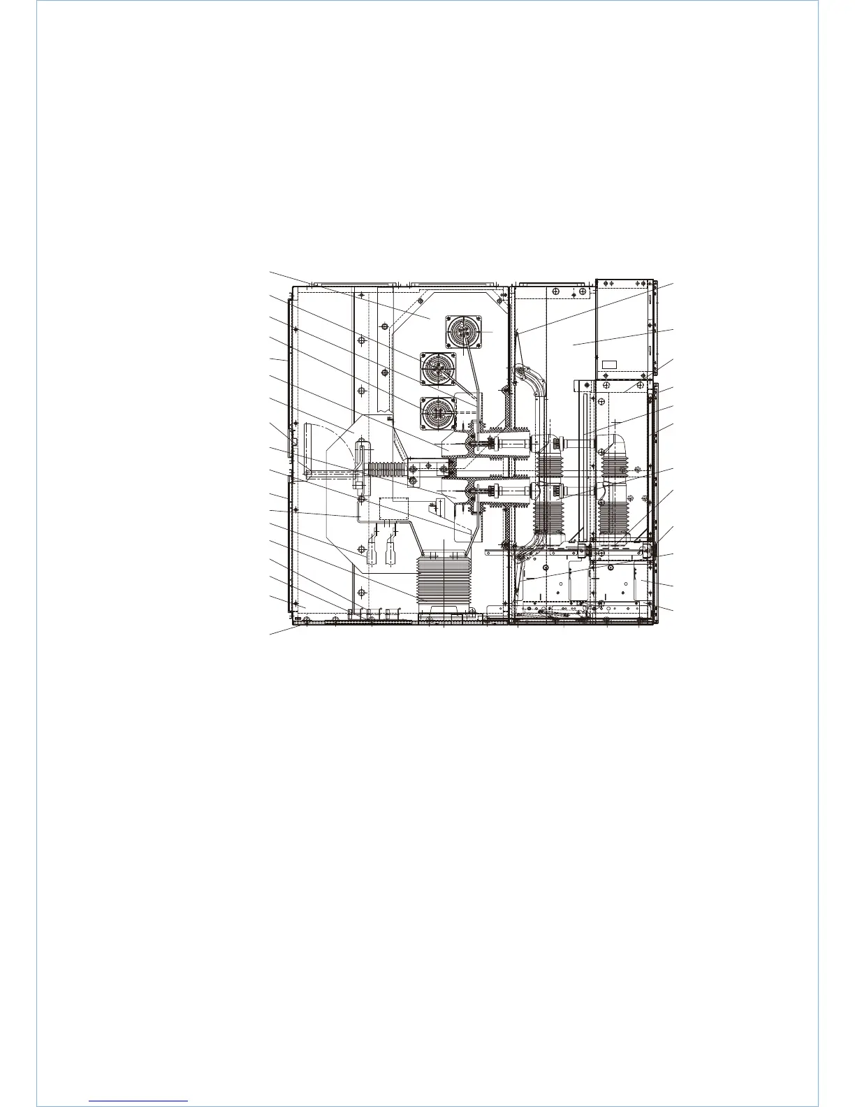
3/6 UniGear ZS3.2
section view, basic
structure of an
incoming or
outgoing feeder
panel, …1600 A
—
3/6
A Circuit-breaker compartment
B Low-voltage compartment
C Busbar compartment
D Cable compartment
1 Enclosure
1.1 Pressure relief plate
1.2 Control wiring duct
3 Busbar
3.1 Tee-off conductor, busbar side
3.2 Tee-off conductor, cable side
5 Insulated separating plate
6 Earthing switch
9.1 Current transformer
10 Control wiring plug connector
10.1 Control wiring socket
10.2 Control wiring plug
10.3 Interlocking arm for wiring plug
14 Earthing switch operation mechanism
14.1 Hexagonal shaft
28
3
3.1
Y(L2)
B(L3)
HEATING PLATE
R(L1)
29
30.1
29.1
5
6
20.2
3.2
30.2
23
16
9.1
21
17.2
19
17
A BC
D
35.1
1
1.2
30
50.2
14, 14.1
50
52
51
35.2
10, 10.1, 10.2
10.3
16 Cable sealing ends
17 Floor cover plate
17.2 Reducer ring
19 Main earthing bar
20.1 Spout, above
20.2 Spout, below
21 Cable clamp
23 Cable connection point
28 Bushing plate
29 Busbar bushing
30 Front door for circuit-breaker compartment
30.1 Rear panel cover, above
30.2 Rear panel cover, below
35.1 Hinged shutter system, above
35.2 Hinged shutter system, below
50 Withdrawable part (with circuit-breaker, type VD4 or HD4)
50.2 Front partition plate
51 Interlock yoke
52 Spindle

 Loading...


