1-14 IP35/IP35-E
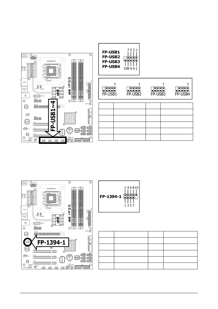
1.8.3 Additional USB 2.0 Port Headers
Each header supports 2x additional USB 2.0 ports by connecting bracket or cable to the rear I/O
panel or the front-mounted USB ports of your chassis.
Pin Pin Assignment Pin Pin Assignment
1 5VDUAL 2 5VDUAL
3 Data0 - 4 Data1 -
5 Data0 + 6 Data1 +
7 Ground 8 Ground
10 NC
※ Make sure the connecting cable bears the same pin assignment.
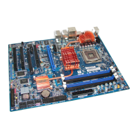
1.8.4 Additional IEEE 1394 Port Header
Each header supports 1x additional IEEE 1394 port by connecting bracket or cable to the rear
I/O panel or the front-mounted IEEE 1394 port of your chassis.
(For IP35 only)
Pin Pin Assignment Pin Pin Assignment
1 TPA0 + 2 TPA0 -
3 Ground 4 Ground
5 TPB0 + 6 TPB0 -
7 +12V 8 +12V
10 Ground
※ Make sure the connecting cable bears the same pin assignment.