Installing the Motherboard 2-11
User’s Manual
Note
Before you clear the CMOS, you have to first turn the power off (including the +5V
standby power). Otherwise, your system may work abnormally or malfunction.
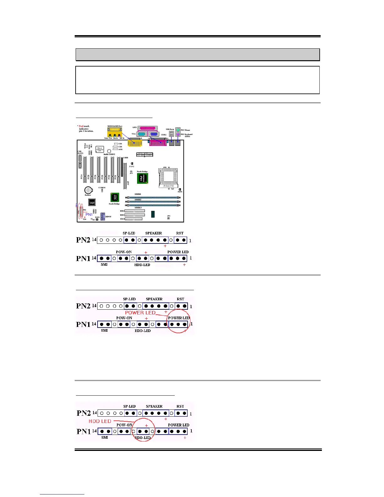
(10) PN1 and PN2 Headers
PN1 and PN2 are for switches and indicators
of the chassis’ front panel. There are several
functions that come from these two headers.
You have to watch the pin position and the
orientation, or you may cause system
malfunctions. Figure 2-7 shows you the
functions of PN1 and PN2.
Figure 2-7. The definition of PN1 and
PN2 pins
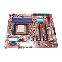
PN1 (Pin 1-2-3-4-5): Power LED Headers
There is a specific orientation for pins 1
through 3. Insert the three-threaded power
LED cable to pins 1~3. Check to make sure
the correct pins go to the correct connectors
on the motherboard. If you install them in the wrong direction, the power LED light will not
illuminate correctly.
Note: Watch the power LED pin position and orientation.
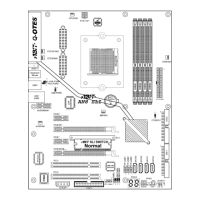
PN1 (Pin 7 - 8): HDD LED Header
Attach the cable from the case’s front panel
HDD LED to this header. If you install it in
the wrong direction, the LED light will not
illuminate correctly.