2-6 Chapter2
SL6
2-4. Connectors, Headers and Switches
Inside the case of any computer several cables and plugs have to be connected. These cables
and plugs are usually connected one-by-one to connectors located on the motherboard. You
need to carefully pay attention to any connection orientation the cables may have and, if any,
notice the position of the first pin of the connector. In the explanations that follow, we will
describe the significance of the first pin.
We will show you all of the connectors, headers and switches here, and tell you how to
connect them. Please pay attention and read the entire section for necessary information
before attempting to finish all of the hardware installation inside the computer chassis.
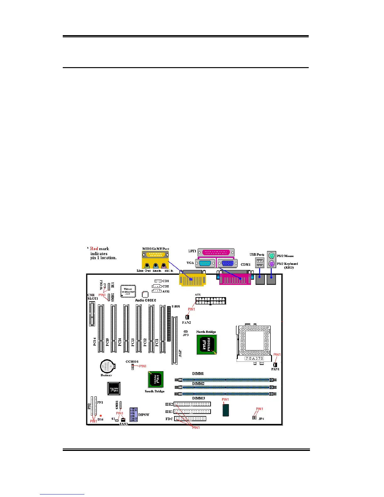
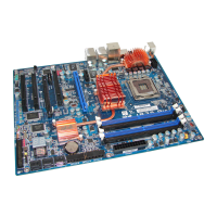
Figure 2-5 shows you all of the connectors and headers that we’ll discuss in the next section,
you can use this diagram to visually locate each connector and header we describe.
All connectors, headers and switches mentioned here will depend upon your system
configuration. Some features you may (or may not) have and need to connect or configure
depending on the peripheral. If your system doesn't have such add-on cards or switches you
can ignore some special feature connectors.
Figure 2-5. All Connectors and Headers for the SL6