Installing the Motherboard 2-13
User’s Manual
Table 2-3. PN1 and PN2 pin count name list
PIN Name Significance of signal PIN Name Significance of signal
PIN 1 +5VDC PIN 1 Ground
PIN 2 No connection PIN 2 Reset input
PIN 3 Ground PIN 3 Empty Pin
PIN 4 No Connection PIN 4 No Connection
PIN 5 No Connection PIN 5 +5 VDC
PIN6 Empty Pin PIN6 Ground
PIN 7 LED Power PIN 7 Ground
PIN 8 HDD active PIN 8 Empty Pin
PIN 9 Empty Pin PIN 9 Speaker Data
PIN 10 Ground PIN 10 No Connection
PIN 11 Power On/Off PIN 11 Empty Pin
PIN 12 Empty Pin PIN 12 No connection
PIN 13 Ground PIN 13 No connection
PN1
PIN 14 Suspend signal
PN2
PIN 14 No connection
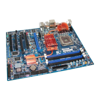
Let’s now see the I/O connectors that the SL6 uses, and what their functions are.
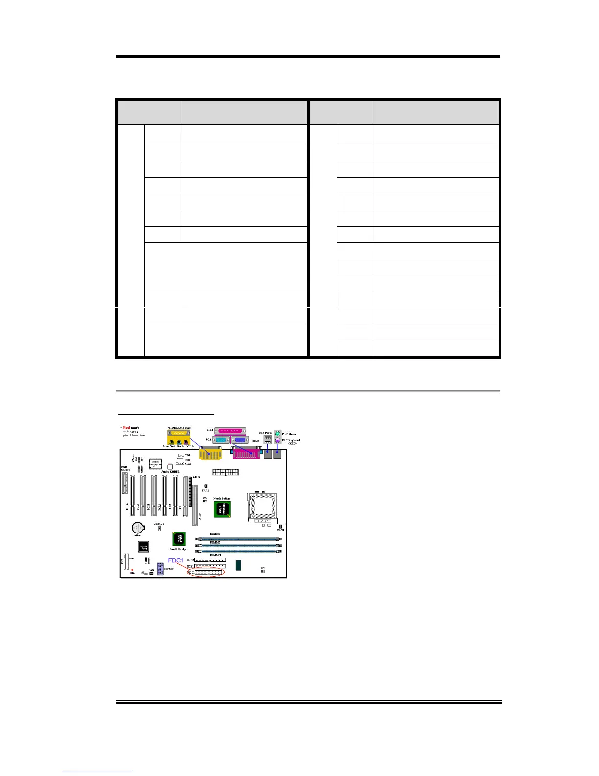
(11) FDC1 Connector
This 34-pin connector is called the “floppy
disk drive connector”. You can connect a
360K, 5.25”, 1.2M, 5.25”, 720K, 3.5’’,
1.44M, 3.5” or 2.88M, 3.5” floppy disk
drive. You can even connect a 3 Mode
floppy disk drive (a 3 1/2” drive used in
Japanese computer systems).
A floppy disk drive ribbon cable has 34
wires and two connectors to provide the
connection of two floppy disk drives. After
connecting the single end to the FDC1, connect the two connectors on the other end to the
floppy disk drives. In general, people only install one floppy disk drive on their computer
system. The end attached to the longer length of ribbon should be attached to the
motherboard connector.