Installing the Motherboard 2-3
User’s Manual
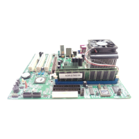
Figure 2-6. Memory module installation
2-3.
Installing System Memory
This motherboard provides three 168-pin DIMM sites for memory expansion. The DIMM
sockets support 1Mx64 (8MB), 2Mx64 (16MB), 4Mx64 (32MB), 8Mx64 (64MB), 16Mx64
(128MB), and 32Mx64 (256MB) or double sided DIMM modules. Minimum memory size
is 8MB and maximum memory size is 768MB SDRAM. There are three Memory module
sockets on the system board. (Total six banks)
In order to create a memory array, certain rules must be followed. The following set of rules
allows for optimum configurations.
!
The memory array is 64 or 72 bits wide. (depending on with or without parity)
!
Those modules can be populated in any order.
!
Supports single and double density DIMMS.
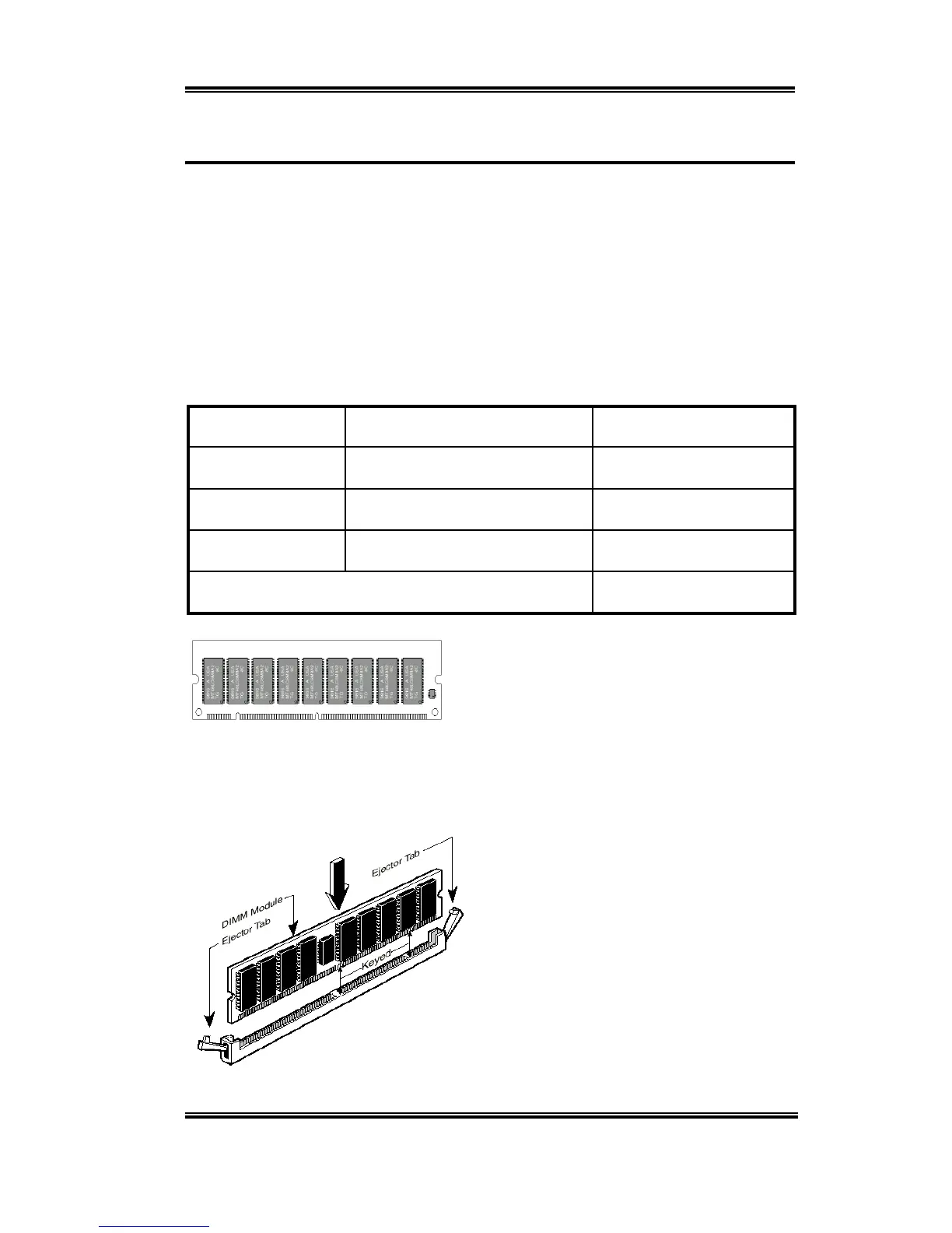
Table 2-1. Valid Memory Configurations
Bank Memory Module Total Memory
Bank 0, 1
(DIMM1)
8MB, 16MB, 32MB,
64MB, 128MB, 256MB
8MB ~ 256MB
Bank 2, 3
(DIMM2)
8MB, 16MB, 32MB,
64MB, 128MB, 256MB
8MB ~ 256MB
Bank 4, 5
(DIMM3)
8MB, 16MB, 32MB,
64MB, 128MB, 256MB
8MB ~ 256MB
Total System Memory
8MB ~ 768MB
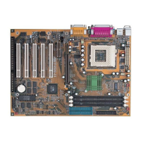
Generally, installing SDRAM modules to your
motherboard is an easy thing to do. You can refer
to figure 2-5 to see what a 168-pin PC100 &
PC133 SDRAM module looks like.
Unlike installing SIMMs, DIMMs may be
"snapped" directly into the socket. Note: Certain
DIMM sockets have minor physical differences.
If your module doesn't seem to fit, please do not force it into the socket as you may damage
your memory module or DIMM socket.
The following procedure will show you how
to install a DIMM module into a DIMM
socket.
Step 1.
Before you install the memory
module, please place the computer power
switch in the
off
position and disconnect the
AC power cord from your computer.
Step 2.
Remove the computer’s chassis
cover.
Step 3.
Before touching any electronic
components, make sure you first touch an
unpainted, grounded metal object to discharge
any static electricity stored on your clothing
or body.
Figure 2-5 PC100/PC133 Module and
Com