Installing the Motherboard 2-11
User’s Manual
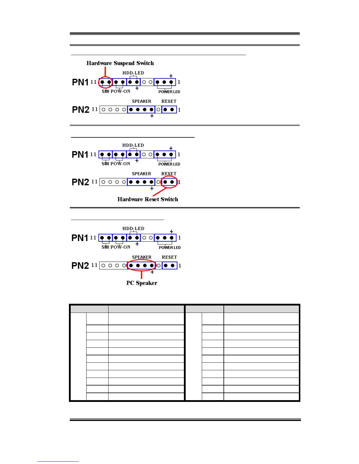
PN1 (Pin 10-11): Hardware Suspend Switch (SMI Switch) Header
Attach the cable from the case’s front panel
suspend switch (if there is one) to this
header. Use this switch to enable/disable the
power management function by hardware.
Note: If ACPI function in the BIOS setup is
enabled, this function will not work.
PN2 (Pin 1-2): Hardware Reset Switch Header
Attach the cable from the case’s front panel
Reset switch to this header. Press and hold
the reset button for at least one second to
reset the system.
PN2 (Pin 4-5-6-7): Speaker Header
Attach the cable from the system speaker to
this header.
For the PN1 and PN2 pin’s count-name list,
please refer to table 2-2.
Table 2-2. PN1 and PN2 pin count name list
PIN Name Significance of signal PIN Name Significance of signal
PIN 1 +5VDC PIN 1 Ground
PIN 2 No connection PIN 2 Reset input
PIN 3 Ground PIN 3 No connection
PIN 4 No connection PIN 4 +5VDC
PIN 5 No connection PIN 5 Ground
PIN6 LED power PIN6 Ground
PIN 7 HDD active PIN 7 Speaker data
PIN 8 Ground PIN 8 No connection
PIN 9 Power On/Off signal PIN 9 No connection
PIN 10 Ground PIN 10 No connection
PN1
PIN 11 Suspend signal
PN2
PIN 11 No connection
Let’s now see the I/O connectors that VL6 uses, and what their functions are.
 Loading...