2.2 Operational principal of boiler
Combustion air is drawn into the inlet connection from the plant room (room ventilated version) or from outside via the
air inlet pipe.
On the inlet side of the fan is a specially designed chamber which takes gas from the multi-block and mixes it in the
correct proportions with the incoming air. This mixing system ensures that the correct gas/air ratio is delivered to the
pre-mix burner at all times.
Depending on demand (under the dictates of ow/return sensor and other external/internal control inputs) The Honeywell
Sola Control varies the speed of the air supply fan which alters the volume of air/gas mixture that is delivered to the
combustion chamber. The resultant controlled mixture is delivered to the premix burner.
This mixture is initially ignited by the combined ignition/ionization probe which monitors the state of the ame. Should
the ame be unstable or not ignite within the pre-set safety time cycle the controls will (after 3 attempts) shut the
boiler down requiring manual intervention to reset the boiler. The display will indicate a ashing fault code 3 times
conrming the reason for the failure.
The products of combustion in the form of hot ue gases are forced through the heat exchanger transferring their heat
to the system water, (the ue gas temperature is reduced to approximately 9-14° F [5-8° C] above the temperature of
the system return water) then discharged via the condensate collector, to the ue gas outlet connection, to atmosphere.
Because of the low ue gas exit temperature there will be a vapor cloud formed at the ue gas terminal – this is not
smoke, simply water vapor formed during the combustion process.
If the ue gas temperature falls below the dew point of 131°F [55°C], water vapor (created during the combustion
process) will begin to condense in the boiler, transferring its latent heat into the system water, thereby increasing the
output of the boiler with-out increasing the gas consumption. Condensation formed within the boiler and ue system
is discharged from the boiler to an external drain via the drain pan and siphon supplied.
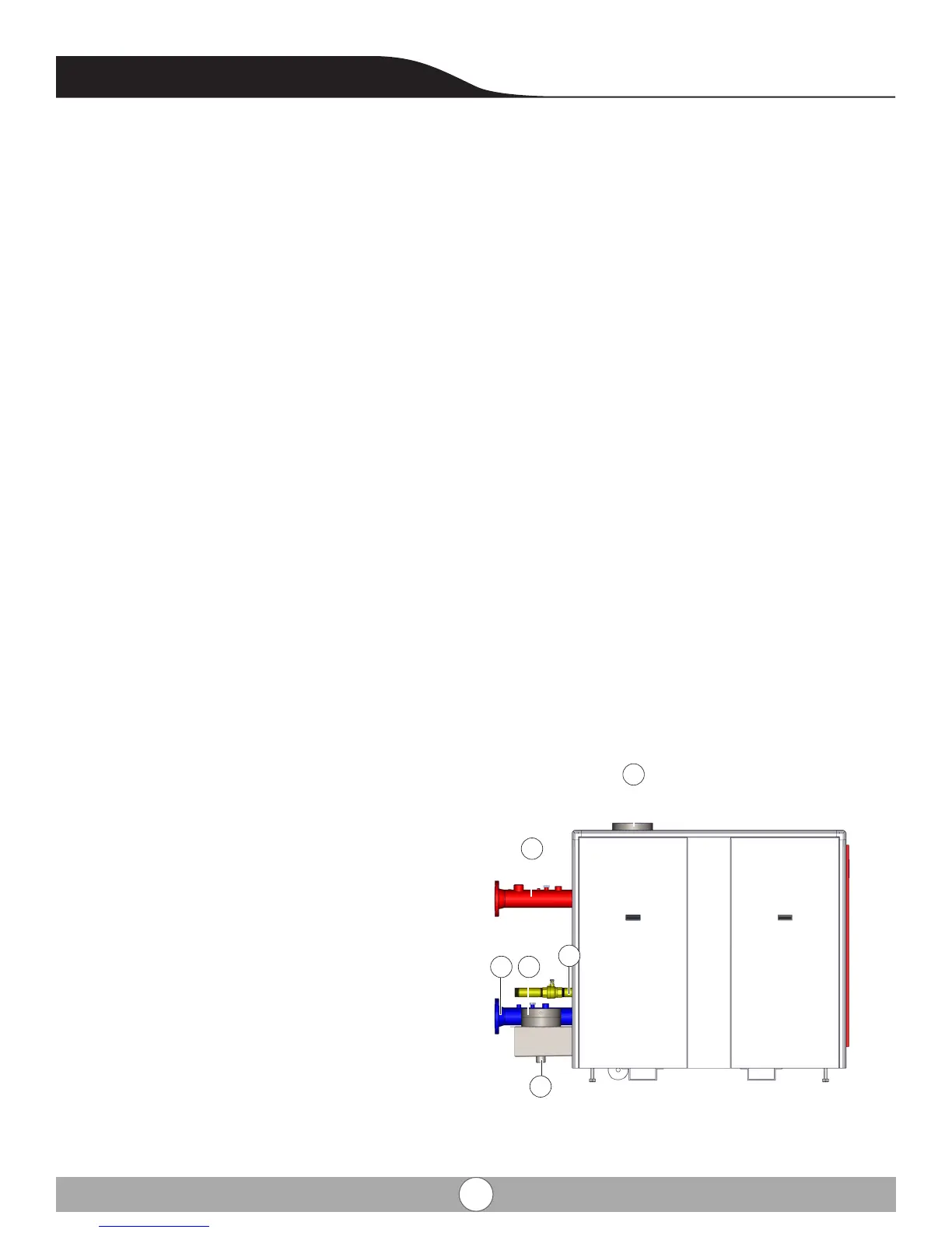
2.3 View of boiler for service connections
A- Combustion air supply connection 10” ID
B- Condensate drain 1 1/4” NPT
C- Flue gas discharge 10” ID
D- Gas connection 2” NPT (manual shut o by others)
E- Supply connection 4” ANSI #150 ange
F- Return connection 4” ANSI #150 ange
A
D
E
CF
B
Absolute Boilers ABS 1500-2000-2500-3000-4000
12