Absolute Boilers ABS 1500-2000-2500-3000-4000
13
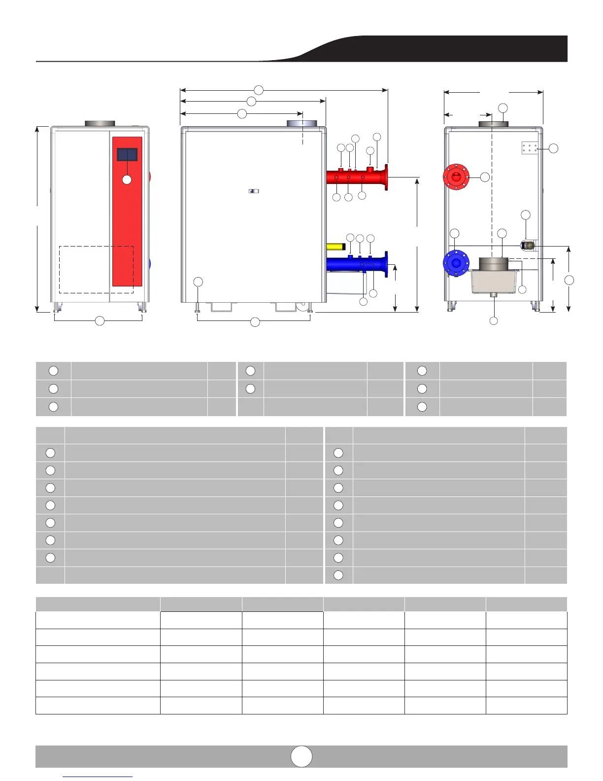
3. Technical Data
Ref.
ABS1500 ABS2000 ABS2500 ABS3000 ABS4000
L 50” 50” 58
1
/
4
” 58
1
/
4
” 69
1
/
4
”
L1 70
11
/
16
” 70
11
/
16
” 77
7
/
8
” 77
7
/
8
” 88
7
/
8
”
Q 22
1
/
2
” 22
1
/
2
” 22
5
/
8
” 22
5
/
8
” 22
5
/
8
”
H* 30” 30” 30” 30” 30”
H1* 38
1
/
2
” 38
1
/
2
” 48” 48” 59”
K 41
5
/
16
” 41
5
/
16
” 43” 43” 43”
A
Boiler Supply (150 ANSI Flanged) 4”
C
Boiler Exhaust Connection 10” ID
E
Combustion Air Inlet 10” ID
B
Boiler Return (150 ANSI Flanged) 4”
D
Gas Connection (NPT male) 2”
F
Honeywell Touch Screen 7”
H
Anchor Bolt 3/4”
J
Wiring Junction
1
/
2
”
Ref. Description Size Ref. Description Size
1
NTC Temperature Sensor (Supply Water)
1
/
2
”
8
Aquastat (Manual Reset)
3
/
4
”
2
Pressure Relief Valve 1
1/2”
9
NTC Temperature Sensor (Return Water)
1
/
2
”
3
Air Vent 1/4”
10
Spare
1
/
2
”
4
Spare
1
/
2
”
11
Spare 1”
5
Flow Switch (Optional) 1”
12
Spare
1
/
2
”
6
Low Water Cut O (Manual Reset)
3
/
4
”
13
Boiler Drain
1
/
2
”
7
Temperature and Pressure Gauge
1
/
2
”
14
Condensate Drain (NPT Female) 1
1
/4
”
15
NTC Flue Gas Sensor
1
/
2
”
18
5
/16
”
46
2
/16
”
16
7
/16”
33
3
/4
”
16
7
/8
”
A
J
E
L1
L
K
B C
D
9
63
1
/2
”
F
H
Boiler
Control
Panel
3
2
6
9
10
12
13
14
15
11
78
1
5 4
H1
Q
H