Absolute Boilers ABS 1500-2000-2500-3000-4000
64
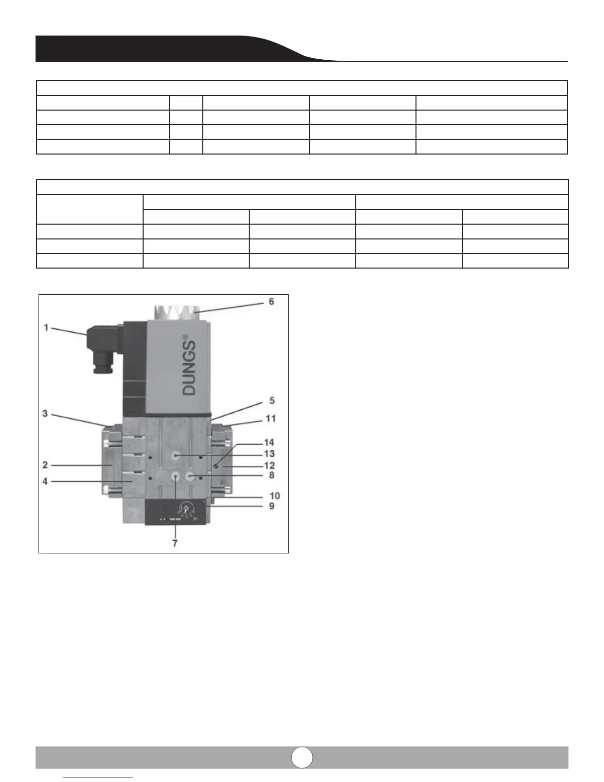
1. Electrical DIN Connector
2. Upstream Flange
3. G1/8 inlet test port
4. Filter
5. Valve Body
6. Coil
7. Test port connection #2, G 1/8 between V1 and V2;
both sides.
8. Test port connection #3, G1/8 downstream of V2;
both sides.
9. Regulator outlet pressure adjustment screw; both side
10. Vent-less regulator vent connection is G1/8 threaded.
The brass vent limiting orice is 0.2mm in diameter.
11. Downstream ange
12. Test port connection #1, G1/8 upstream of V1; both
sides.
13. Oset adjustment cover
Combustion Readings
Emission Unit Range Part Load (20%) Full Load (100%)
CO2 Range % 6 - 9.5 8.0 9.0
O2 Range % 8.0 – 4.0 7.0 5.0
CO Limit ppm < 100
Gas Pressure Readings
Full Load (100%) Part Load (20%)
Δp [in w.c.] Δp [mbar] Δp [in w.c.] Δp [mbar]
EPN/EPAW1050
EPN/EPAW1600
EPN/EPAW2080
9.4 IMPORTANT SAFETY WARNING:
The installation of the boiler is not completed until all controls and safety device have been tested and
veried for correct function and operation. It is the sole responsibility of the installer to ensure that
safety control system and gas ignition system and any there safety control must be tested
Note:
Absolute is supplied with a number of factory default settings that should be correct for most installations. If there
setting values are required: The following operating situations are now possible: