Absolute Boilers ABS 1500-2000-2500-3000-4000
56
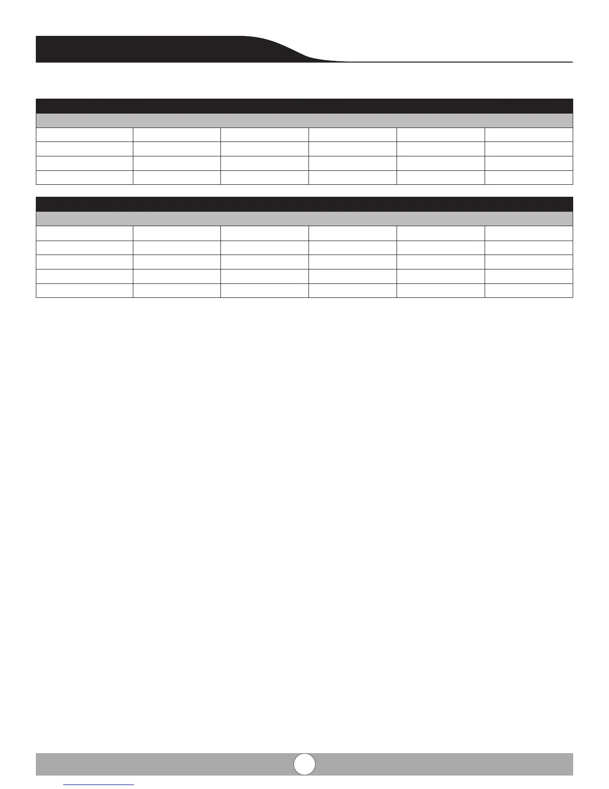
7.3 Combustion setting and adjustment
Factory combuson readings Chart 8
Set point
High re ABS 1500 ABS 2000 ABS 2500 ABS 3000 ABS 4000
CO2 9.7 9.58 9.3 9.3
CO ppm 65 87 65 54
O2 3.6 9.58 4.3 4.3
Factory combuson readings Chart 8
Set point
Set point
Low re ABS 1500 ABS 2000 ABS 2500 ABS 3000 ABS 4000
CO2 7.8 7.96 8.63 7.4
CO ppm 23 12 5 15
O2 7 6.6 5.5 7.7
Check and correct, if necessary, the boiler for correct gas/ air rao set-up. Checking takes place on full and part load, ad-
justment takes place only on the gas valve mono block. For checking and adjusng are required: an electronic CO2-gauge
(on the basis of O2) and a gas pressure gauge. Note that the opening (see g. 23) around the measuring probe is sealed
properly during measurement. Note also that measuring the O2 levels in the ue gas is necessary, because direct mea-
surement of CO2 can lead to inaccuracies due to varying CO2 levels in the natural gas. Connect the gas pressure meter
between measuring point PG on the underside of the gas valve mono block and measuring point PL on the venturi (see
g. 23), ensuring the connecons are gas ght.
Check CO2- percentage (O2-percentage) against table
8. If the values exceed the given tolerances, adjust according to g. 23. Check the ame through the inspecon glass, the
ame must not blow o.
Check the ame through the inspecon glass, the ame must not blow o. Repeat the check starng from point