Absolute Boilers ABS 1500-2000-2500-3000-4000
47
H
G
F
E
D
C
B
A
8 7 6 5 4 3 2 1
H
G
F
E
D
C
B
A
8 7 6 5 4 3 2 1
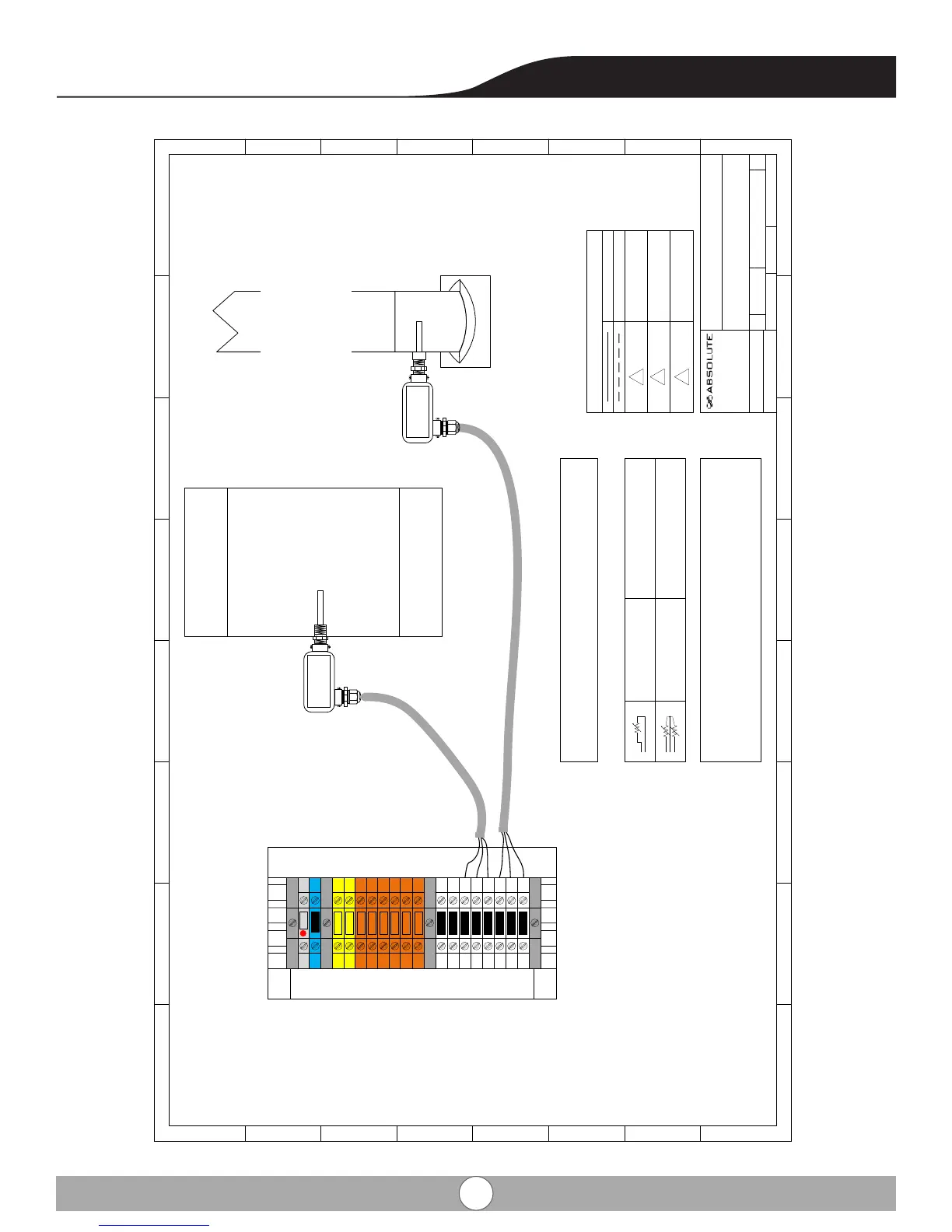
Absolute ABS Series (All Models)
Typical Field Wiring
Optional Sensor wiring (DHW tank, Flue Sensor)
SIZE Drawn by: DWG NO REV
11x17
Craig H. 4-EPA-SOL-001 0
SCALE
NTS 4/6/2016
SHEET
15 OF 15
DHW sensor (Optional) 50001464-006
(installed on EPA supply manifold or storage tank sensor well)
DDR Kit # ___________
Flue Gas Temp sensor (Optional) 50001464-006
DDR kit # ____________
1
(-)
(+)
TT
TT
ON
ON
OFF
OFF
OD
DHW
+24
24 N
DHW
DHW
OD
FL
FL
FL
TB2
Internal Wiring
TB2
Caution No don’t apply power
Sensor Wiring Only
Main 24v Power
Control/Display
Remote Automatic
Connections
Wiring Legend
Power wiring min 18awg
Sensor wiring shielded type
Pump Control
Dry contacts rated 5A max
Remote BMS 24v enable/
disable
120v safety contact
1
2
3
Single sensor
(Non safety)
Dual sensor
(Safety)
Supply,
DHW & Flue
Return, Outdoor &
Common Sensor
Hot Water
Storage Tank
DHW
Sensor
3/c shielded cord 18-22 awg.
3
/
c
s
h
i
e
l
d
e
d
c
o
r
d
1
8
-
2
2
a
w
g
.
Optional wiring shown “By Others”
Field wired and installed
Not all wiring shown
DHW & Flue sensor 100 ft. wiring cable
provided with each kit.
Flue
Sensor
Optional Flue temperature
sensor Required for Non
metallic vent systems
Innovative Industrial Inc.
122 Burton Street, Hamilton,
Ontario, Canada L8I 3R5