Fire Ready Hood 15
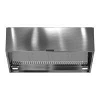
Manual Pull Station (if applicable)
Manual pull station will be provided with a 30 ft. plug
and play cable. Run this behind the wall through a
one inch knockout in the controls j-box, then into the
hood and connect to “REMOTE PULL” port on fire
suppression control board.
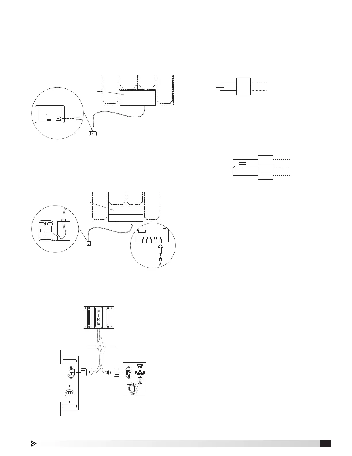
RANGE
115 VOLT - 15 AMP
ALARM / STROBE
115 VOLT - 5 AMP
LEFT SIDE VIEW -
GAS SHUT OFF
ASSEMBLY BOX
(MOUNTED BEHIND RANGE)
OR
LEFT SIDE VIEW -
ELECTRIC SHUT OFF
ASSEMBLY BOX
(MOUNTED BEHIND RANGE)
HORN STROBE
8 FT. CABLE
FIRE
FIRE READY
HOOD
USER
INTERFACE
BACK OF USER
INTERFACE
R12
TELEPHONE
CONNECTOR
8.5 FT. CABLE
ATTACHED TO
HOOD
FIRE READY
HOOD
VALV E
(TANK SOLENOID)
REMOTE
PULL
RF
BLDG
ALARM
SHUT-OFF
30 FT. CABLE
PLUGS INTO
"REMOTE PULL" ON
FIRE SUPPRESSION
CONTROL BOARD
INSIDE
HOOD
MANUAL PULL
STATION
INSIDE MANUAL
PULL STATION
J-BOX
PULL
FIRE FIRE
Other External Devices
Supply Fan Interlock Contacts
1. R and G terminal
2. Dry, normally open contact closes when supply
fan should run – can be used to drive a device that
controls a supply fan if MUA is necessary
3. Contacts rated to 5A and 250VAC
Fire/Fault Contacts
1. C6 and NO6 terminal blocks - Dry, normally open
(N.O.) contact closes on fire/fault
2. C6 and NC6 - Dry, normally closed (N.C.) contact that
opens on fire/fault
3. Contacts rated to 5A and 250VAC
C6
NO6
U1 PLC
CONTACT
NC6
R
G
14
11
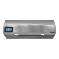
Horn Strobe (if applicable)
There will be one 8 ft. plug and play cable attached
to the horn strobe itself. Run the cable to the gas or
electric shut off assembly box and connect to the
receptacle labeled “ALARM / STROBE”.
Accessories
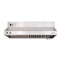
Remote Mounted User Interface (if applicable)
There will be one 8½ ft. plug and play cable with an
light blue label attached to the hood. Run the cable
through a one inch knockout in the controls j-box,
run behind the wall and connect to the back of the
user interface. Mounting instructions can be found on
page11.
See page 18 for additional details.
 Loading...