Fire Ready Hood 3
Example: XRRS-W-36-T-E-O-N
Accurex XRRS, wall mount, 36 inches long, with top
discharge, with electric element disconnect, fan
provided by others, NFPA 101 Compliant
XRRS - W- 36 - T - E - O - N
Model
Residential
Range
Suppression
Configuration
W - Wall
I - Island
Ventilation
F - Integral Fan - Front Recirculation
R - Integral Fan - Rear Discharge
T - External Fan - Top Discharge
External Fan Type
D - Inline Duct
O - Fan by Others
NFPA 101 Compliance
X - Noncompliant
N - Compliant
Range Disconnect Type
E - Electric
G - Gas
Length
30 inches
36 inches
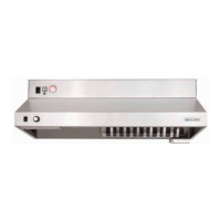
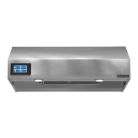
Model Number Code
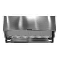
Hood Exploded View
TOUCHSCREEN
USER INTERFACE
WALL MOUNT
BRACKET
RECIRCULATING VENT
(FRONT RECIRCULATING MODEL)
WALL CLAMP
(QTY 2)
HOOD TEMPERATURE
SENSOR
LED LIGHTS
(QTY 2)
FIRE SUPPRESSION
TEMPERATURE SENSORS
(QTY 2)
GREASE FILTER
FIRE SUPPRESSION TANK AND
SOLENOID RELEASE
FIRE SUPPRESSION
CONTROL BOARD
INTERNAL EXHAUST FAN
(FOR FRONT RECIRCULATING
AND REAR DISCHARGE MODELS)
HOOD CONTROLS
(PLC, RELAYS, AND
TERMINAL BLOCKS)
FIRE SUPPRESSION
DROPS WITH NOZZLES
(QTY 2)
MODEL / SERIAL #
INFORMATION
STICKER
Table of Contents
Receiving, Unpacking, Parts Checklist,
Handling and Storage ...................... 2
Model Number Code ......................... 3
Hood Exploded View ......................... 3
Ventilation and Fan Type Configurations ......... 4
Installation
General Information and Hood Weights ........ 7
Dimensional Data and Mounting Bracket ....... 8
Ductwork ................................ 9
Hood ................................... 9
External Fan ............................. 10
Range Disconnect
Gas / Electric ........................... 10
Accessories
Remote Mounted User Interface ............ 11
Finished Top ............................ 11
Ceiling Enclosures ....................... 11
Wall Cap ............................... 11
Manual Pull Station ...................... 12
Horn Strobe ............................ 12
Fire Extinguisher ........................ 12
Electrical Connections
Hood Power ............................. 13
Fan Power - Integral or External Fan .......... 13
Range Disconnect
Gas / Electric .........................13-14
Accessories
Remote Mounted User Interface ............ 15
Manual Pull Station ...................... 15
Horn Strobe ............................ 15
Other External Devices
Supply Fan Interlock Contacts ............. 15
Fire/Fault Contacts ...................... 15
Fan Calibration ........................... 16
Aiming the Nozzles ....................... 17
Operation ................................. 17
Unit Pre-Suppression Functions ............. 17
Arming the System. . . . . . . . . . . . . . . . . . . . . . . . 18
User Interface Navigation
Hood Lights Operation ................... 20
Fan Operation .......................... 20
Range Operation ........................ 20
Fire System Discharge .................... 21
System Faults .......................... 21
Service Settings .......................21-23
Fire Prevention Tips ...................... 23
Service and Maintenance
Accessing Internal Components ............. 24
Fire System Diagnostics ................... 25
Fire System Shut Off Sequence ............. 25
Fire System Detect Mode .................. 25
Fire Alarm Sequence ...................... 26
After Actuation ........................... 26
Routine Maintenance ....................... 27
Troubleshooting ..........................28-29
Parts List ................................. 29
Our Commitment .....................Backcover
 Loading...