Fire Ready Hood10
Range Disconnect
Gas (if applicable)
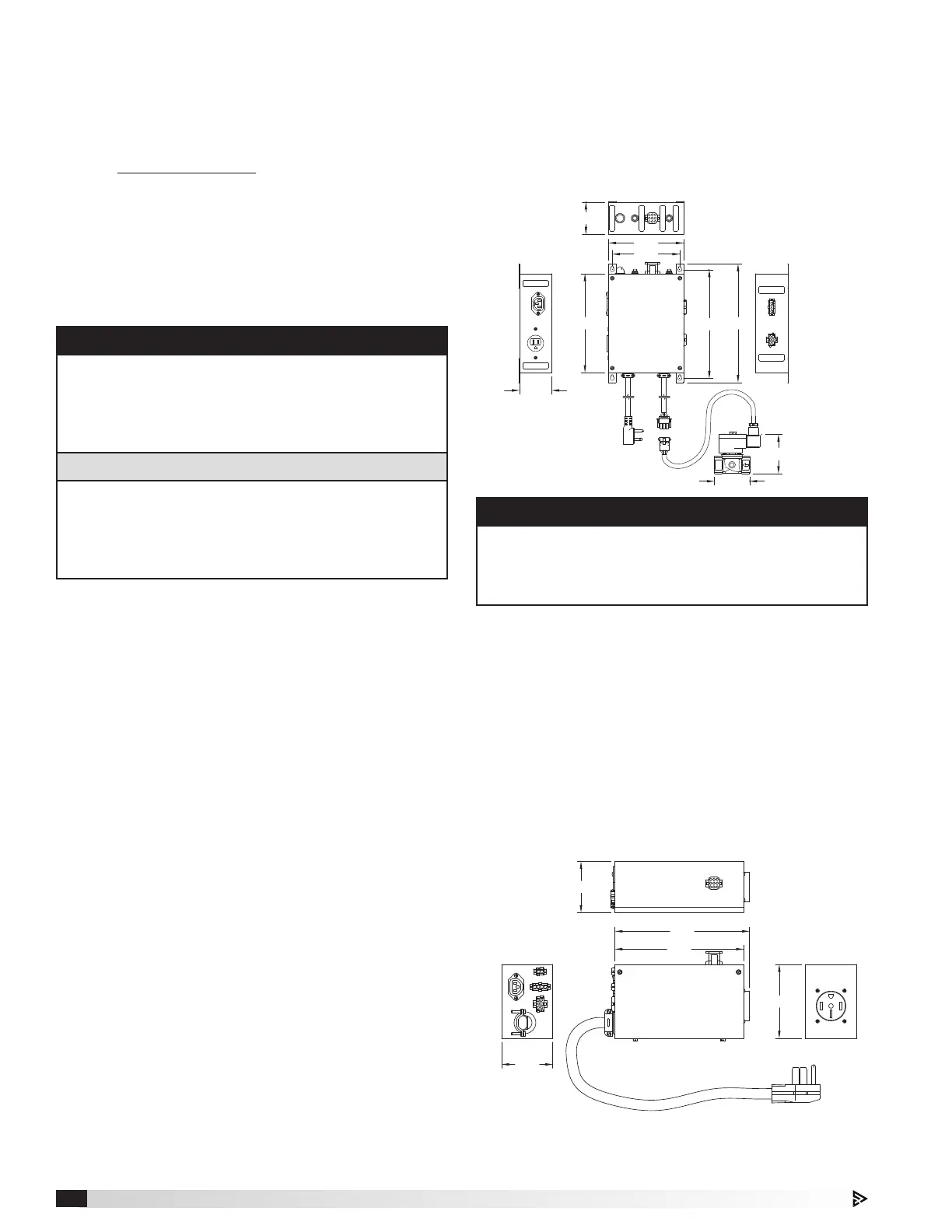
1. Locate gas shut off assembly box and gas valve.
2. Using the four (4) appropriate sized fasteners, mount
and fasten gas shut off assembly box behind range
through mounting holes provided. Unit dimensions
shown:
3. If not already done, plug gas valve 1.5 ft. whip into
5 ft. gas valve cord coming off of bottom of the gas
shut off assembly box. Install ¾ inch (NPT fittings)
gas valve in-line with gas line to range.
4. Follow electrical installation instructions for gas range
disconnect on pages 13 and 14.
Electric (if applicable)
1. Locate electric shut off assembly box.
2. Electric shut off assembly should be situated behind
the range (on floor) or in cabinet next to range. Unit
dimensions shown:
3. Follow electrical installation instructions for electric
range disconnect on page 14.
3/4"
6.25
10.00
9.19
8.25
5.60
RANGE
115 VOLT - 15 AMP
ALARM / STROBE
115 VOLT - 5 AMP
2.70
GAS FLOW
VALVE RESET
POWER RESET
FUEL ACTIVATION
CONTACT RATING
12 VAC - 5 AMP
AUXILIARY INTERFACE
CONTACT RATING
115 VAC - 5 AMP
2.70
60 IN. (5 FT)
POWER CORD
WITH 5-15R PLUG
3/4 IN. NPT
GAS
VALVE
18 IN. (1.5 FT)
WHIP TO
GAS VALVE
60 IN. (5 FT)
GAS
VALVE
CORD
3.00
3.32
LEFT SIDE
VIEW
RIGHT SIDE
VIEW
TOP VIEW
GAS SHUT OFF
ASSEMBLY BOX
(FRONT VIEW)
GAS /ELEC DISC
CABLE
Dimensions shown
are in inches.
9.00
9.38
3.75
5.32
3.75
ELECTRIC SHUT OFF
ASSEMBLY BOX
(TOP VIEW)
BACK VIEW
LEFT SIDE
VIEW
RIGHT SIDE
VIEW
30" (2.5 FT)
POWER CORD
WITH 14-50 PLUG
Dimensions shown are in inches.
NOTE
Cables provided to connect the gas assembly box
back to the hood are 10 ft. long. Do not mount the gas
shut off assembly box too far away from the hood, as
these cables will not reach.
External Fan (if applicable)
External Fan – Inline
Install fan vertically or horizontally in ductwork running
between the unit and roof cap. Make sure the fan
installed with the airflow arrow on the side of the fan
directed away from the hood (to the outside).
For best results, use as few elbows or transitions as
possible. If necessary, long radius elbows or bends are
recommended.
To attach ductwork, use duct tape at inlet and outlet to
assure a good seal. If using fan clamps, attach clamps
and insert screws through clamp into inlet and outlet
flanges.
External Fan – Fan By Others
Follow all installation instructions provided with the fan.
CAUTION
Use sheet metal screws to secure ductwork to inlet
and outlet. It is critical that the screw penetrate the
metal of the flange, but not so far as to bind the
impeller. It may be necessary to angle screws away
from impeller.
ATTENTION
Utiliser des vis autotaraudeuses pour fixer le réseau de
gaines à l’entrée et à la sortie. Il est essentiel que la vis
pénètre le métal du rebord, mais pas assez pour faire
saisir la turbine. Il peut être nécessaire de faire dévier
les vis pour les éloigner de la turbine.
 Loading...