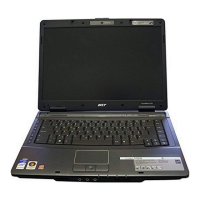
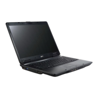
Do you have a question about the Acer Extensa 2000 and is the answer not in the manual?
Details the computer's key features and capabilities.
Provides a visual representation of the system's internal components.
Illustrates the physical arrangement of components on the motherboard.
Describes the ports and external connectors available on the computer.
Explains the status icons and their meanings.
Details the keyboard layout, special keys, and functions.
Lists keyboard shortcuts for system controls and utilities.
Lists detailed technical specifications of the computer's components.
Guides users through the BIOS configuration program.
Explains how to move through and interact with the BIOS menus.
Displays detailed system hardware information within the BIOS.
Shows basic system hardware summary and setup parameters.
Configures advanced hardware device settings and system options.
Manages system passwords and security features.
Sets the order of devices for system startup.
Options for saving, discarding, or loading BIOS settings.
Instructions for updating the system BIOS firmware.
Provides essential precautions before starting disassembly.
Outlines the sequence for removing internal components.
Step-by-step guides to safely remove the computer's battery and RAM.
Covers removal and disassembly of HDD and LCD components.
Procedures for accessing and removing key internal components of the main chassis.
Instructions for upgrading the system with a wireless unit.
Guides for diagnosing issues with drives and input devices.
Steps to diagnose issues related to RAM modules and power sources.
Diagnosing touchpad issues and understanding POST error codes.
Comprehensive lists of error codes, symptoms, and troubleshooting actions.
Strategies for diagnosing and resolving recurring or unclear system issues.
Guides for creating system recovery disk images and data recovery.
Identifies jumpers and connectors on the motherboard's top, bottom, and switch settings.
Visual breakdown of system components for identification.
Lists parts and part numbers for Extensa 2000 and 2500 models.
Lists hardware configurations for Extensa 2000 and 2500 models.
Lists hardware components tested for Windows XP compatibility.
| CPU | Intel Celeron |
|---|---|
| Optical Drive | DVD-ROM |
| Networking | 10/100 Mbps Ethernet |
| Ports | VGA |
| Battery | Lithium Ion |
