Do you have a question about the Acer P205H and is the answer not in the manual?
General safety guidelines for monitor operation and handling.
Specific safety notices regarding replacement components and hazards.
Notes for service personnel on wire handling and adjustments.
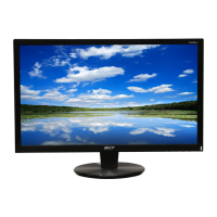
Overview of the LCD monitor features and capabilities.
Detailed technical specifications of the monitor's display and performance.
List of included accessories with the monitor.
Conditions for display quality and operation.
Temperature and humidity ranges for operation and storage.
Compliance and requirements for safety, EMC, ergonomics, and compatibility.
Specifies requirements for protection against electrostatic discharge.
Information on Mean Time Between Failures (MTBF) and LCD panel life.
Detailed input and output characteristics of the power supply.
Specifications for ripple, noise, voltage, and timing of power outputs.
Details on over-power, short-circuit, and over-voltage protection.
Specifications for the backlight unit's power supply and components.
Test conditions and requirements for brightness output measurement.
Test conditions for white balance and chromaticity coordinates.
Method and definition for measuring brightness uniformity.
Specifications for the optional audio input signal.
Detailed specifications for video and signal timing inputs.
Description of control button functions and their operations.
How to use hot keys for specific functions like e Color and Power.
Overview of the On-Screen Display menu structure and default values.
OSD settings for display mode, aspect ratio, and source selection.
Supported languages for the OSD interface.
Information display for resolution, frequency, and input type.
Equipment and ESD requirements for firmware upgrading.
Step-by-step procedure for upgrading the monitor firmware.
Overall description of the LCD panel technology and capabilities.
Key features of the TFT LCD panel, such as contrast and response time.
Common applications and usage scenarios for the LCD panel.
Physical and display characteristics of the LCD panel.
Electrical and environmental limits to prevent damage.
Specified ranges for temperature and humidity for operation and storage.
Electrical characteristics for the TFT LCD module interface.
Block diagram of the TFT LCD module components and connections.
Block diagram illustrating the back light unit configuration.
Pin assignment details for input signals and power connections.
Signal interface details for odd pixel data transmission.
Signal interface details for even pixel data transmission.
LVDS transmitter signal interface for odd pixel data.
LVDS transmitter signal interface for even pixel data.
Key timing parameters for DE only display mode.
Guidelines for safe handling and assembly of the LCD module.
Recommended conditions for storing the LCD module.
Rules for connecting/disconnecting and operating the module.
Guidance on operating conditions and extreme environment usage.
Additional precautions regarding UV rays, condensation, and image sticking.
List of screws used for assembly with part numbers and specifications.
Visual representation of the LCD module components and their assembly.
Component layout diagram for the main Printed Board (Top/Bottom).
Component layout diagram for the Interface Board (Top/Bottom).
Schematic and layout for the switching mode power supply section.
| Pixel pitch | 0.276 x 0.276 mm |
|---|---|
| Aspect ratio | 16:9 |
| Display diagonal | 20 \ |
| Display resolution | 1600 x 900 pixels |
| Contrast ratio (dynamic) | 20000:1 |
| Contrast ratio (typical) | 250:1 |
| Viewing angle, horizontal | 160 ° |
| Display brightness (typical) | 300 cd/m² |
| Power management | ENERGY STAR |
| Display viewable area (HxV) | 443 x 249 mm |
| Mean time between failures (MTBF) | 50000 h |
| HDCP | Yes |
| Certification | CE, TÜV GS, MPRII, ISO 13406-2 |
| Product color | Black |
| Market positioning | - |
| LED indicators | Stand-by |
| Tilt angle range | -5 - 15 ° |
| Panel mounting interface | 100 x 100 mm |
| Power consumption (off) | 0.75 W |
| Power consumption (standby) | 0.97 W |
| Power consumption (typical) | 28 W |
| Depth (without stand) | 190.5 mm |
|---|---|
| Width (without stand) | 478 mm |
| Height (without stand) | 367.5 mm |
| Weight (without stand) | 4200 g |